
In polymer additive manufacturing, Selective Laser Sintering (SLS) has quietly become the default route for "truly usable parts straight out of the printer." The reason is structural: the unsintered powder surrounding each layer acts as its own support, allowing overhangs, undercuts, internal channels, living hinges, and even in-situ printed active components to be formed directly, without the need for extensive destructive support structures. The trade-off is that material selection and post-processing must be disciplined—the surface fresh out of the machine is matte and slightly porous, and the five families of materials available on modern SLS platforms span two orders of magnitude in rigidity. This article will address how to choose the material family, how to design based on the numbers the process can truly deliver, and which post-processing steps are essential when parts are to be delivered to customers.
The True Value and Inherent Limitations of SLS
SLS has its place in the mass production toolbox because of the powder bed itself: geometric freedom without needing supports, nesting economics that amortize per-part costs by filling the bed, and mechanical properties approaching injection-molded nylon levels—sufficient for validating assemblies. But the same process also has its limitations: the surface fresh out of the machine is somewhat matte and grainy; parts have a porosity of a few percent, which will absorb dyes, oil, and hand stains unless sealed; and the risk of contamination from powder handling is not present in FDM and SLA. In practical projects, printing and post-processing time must be scheduled together, and the aesthetic surface treated as a formal design step, not an afterthought.
| Advantage | Cost / Consideration | Engineering Significance |
|---|---|---|
| Geometric freedom without support limitations | Residual powder in deep cavities must be removed | Closed spaces require powder removal holes ≥ 4 mm |
| Usable mechanical properties straight out of the machine | Part porosity is approximately 5–8% | Seal or dye when in contact with fluids, skin, or for aesthetic purposes |
| Amortize per-part cost by filling the bed | Different thermal histories at various positions within the build chamber | Critical tolerance features should be placed in thermally stable areas |
| Living hinges and in-situ assemblies can be printed directly | Handling can cause powder particles to adhere | Always bead blast before shipping; allow 24h post-processing buffer in schedule |
| Wide range of material families—from elastomers to glass-filled composites | Ductility decreases faster with higher fill ratios | Choose family based on dominant load, not just datasheet tensile values |
Why the Difference Between SLS and MJF Matters
SLS and MJF are often discussed in tandem, and for some parts, they are indeed interchangeable, but they are not the same process. SLS uses a laser to melt powder layer by layer; MJF jets a fusing agent onto the powder bed and then uses an infrared lamp to melt the marked areas. This difference in mechanism directly reflects in density, surface, and color. MJF parts have slightly higher density (approx. 1.01 g/cm³ compared to SLS's 0.90–0.95 g/cm³), slightly lower porosity (overall approx. 6% vs. SLS's 8%), and a slightly finer surface finish straight out of the machine. However, MJF only comes in black (or gray with an external agent), and the dyeing effect is not as uniform as SLS. SLS can use white, offering greater dyeing flexibility. Decision rule: if aesthetic color is important, or if dyeing to other colors is required, choose SLS; if aesthetic color is not an issue and slightly higher density and detail are desired, choose MJF.
| Comparison Item | SLS | MJF |
|---|---|---|
| Melting Mechanism | Laser scanning layer by layer | Fusing agent + infrared lamp |
| Part Density | Approx. 0.90–0.95 g/cm³ | Approx. 1.01 g/cm³ |
| Porosity | Approx. 8% | Approx. 6% |
| Out-of-machine color | White powder | Dark gray/black |
| Dyeing Flexibility | High (white base) | Low (black base, mostly dark colors only) |
| Surface Detail | Slightly coarse | Slightly fine |
| Suitable Scenarios | Aesthetic color important, needs dyeing | Black or dark aesthetic, seeking slightly higher density |
SLS Material Landscape
There are five families of mass-producible SLS materials. The quickest path to selecting the right material is to first consider the dominant loading type—is the part subjected to rigid loads? Repeated flexing? Sealing fluids? Or skin contact?—and place the tensile strength from the datasheet in a secondary, rather than primary, position. The table below summarizes the typical engineering properties of each family, and the following sections explain when each family is the right choice.
| Material Family | Representative Grade | Tensile Strength (MPa) | Elongation at Break (%) | HDT (°C) | Positioning |
|---|---|---|---|---|---|
| PA12 | EOS PA 2200, Sinterit PA12 | 48 | 18 | 163 | General engineering, default for most SLS projects |
| PA11 | EOS PA 1101 | 48 | 45 | 200 | High ductility, impact resistance, long fatigue life |
| Glass-filled PA12 | EOS PA 3200GF | 51 | 4 | 180 | High rigidity, dimensional stability, heat resistance |
| Polypropylene (PP) | Sinterit PP, EOS PP | 18 | 40 | 100 | Chemical resistance, fatigue resistance, low modulus alternative to PA12 |
| TPU | Sinterit Flexa Grey | ~8 | > 100 | — | Elastomer: seals, gaskets, vibration damping |
PA12: The Default Workhorse
PA12 is at the heart of almost every SLS project because it strikes a balance of strength, dimensional stability, and chemical resistance superior to any other single powder. It prints stably, retains tolerances, dyes cleanly, and can withstand the mechanical loads of most functional prototypes and small batch production parts. Practically, this family comes in three types: standard white (most consistent mechanical properties), black (usually dyed black from white, color is superficial and will wear off with long-term use), and economic (increased recycled powder ratio to lower cost, at the expense of slight mechanical consistency). Unless specific requirements push you away from PA12, start here.
PA11: When Ductility is the Star
When the requirement is for repeated flexing, impact resistance, or not cracking under large strains, PA11 is the one to reach for. Its elongation at break is roughly double that of PA12, which is why it is chosen among SLS nylons for living hinges, wearable contact parts, shoe midsoles, prosthetic sockets, and any assembly that will be latched, bent, or stretched. The trade-off is a unit cost about 25–40% higher than PA12, and slightly lower room temperature rigidity—a cost usually acceptable when PA12 parts would simply break.
Glass-Filled PA12: High Rigidity and Dimensional Stability
Adding about 40% glass beads to PA12 can almost double the modulus, increase the heat deflection temperature, and significantly reduce the tendency for warping in large flat parts. This is the material of choice for jigs, fixtures, structural brackets, and stressed or heated enclosures. The trade-off is impact resistance and ductility: where unfilled PA12 would deform on thin sections, glass-filled PA12 will brittle fracture, and a 0.5 mm snap-fit often breaks on the first use when printed with GF. GF is specifically for rigid structures; do not use it for features requiring flexibility.
Polypropylene (PP): Chemical and Fatigue Resistance
When parts will contact acids, solvents, fuels, or require repeated flexing fatigue where nylon hinges would crack, SLS polypropylene is the answer. It is weaker than PA12 in pure tensile metrics (approx. 18 MPa vs. 48 MPa), but absorbs almost no water—maintaining stable dimensions and mechanical properties in humid or immersed environments—and has a better repeated flex life than any nylon. Typical applications include fluid connectors, caps, chemical-resistant shields, nozzles, and active hinge covers requiring tens of thousands of cycles.
TPU: Elastomers for Sealing and Soft Touch
TPU powder lies at the other end of the rigidity spectrum. With a tensile modulus of approximately 40–90 MPa and elongation at break over 100%, it is practically an elastomer—suitable for gaskets, damping blocks, shock absorption zones, and soft-touch grips for geometries that cannot be made with silicone or cast polyurethane. TPU has almost no structural rigidity; designs should treat it as a "flexible interface attached to a rigid part," not as a primary load-bearing element.
DFM Values for Practical Use
The powder bed itself has geometric minimums; parts designed below these minimums will form but behave differently than expected in CAD. The table below lists safe default values for industrial SLS PA12; PA11 and PP can be slightly thinner, while glass-filled PA12 is recommended to increase each minimum by approximately 30%. Any enclosed internal volume must have powder removal holes—residual powder will add weight, accumulate heat during use, and even leak powder months after delivery.
| Feature | Recommended Minimum (PA12) | Description |
|---|---|---|
| Structural Wall Thickness | 1.0 mm | 0.7 mm possible for short spans; over 100 mm prone to warping |
| Supported Rib / Column | 0.8 mm | Aspect ratio should be kept below 8:1 to prevent curling |
| Embossed / Debossed Features | 0.5 mm width × 0.8 mm height | Sans-serif fonts are more legible |
| Hole Diameter | 1.5 mm | Will be approx. 0.1 mm smaller; critical holes require reaming |
| Clearance for Moving Parts | 0.4–0.5 mm | 0.4 mm is practical minimum; 0.6 mm withstands dyeing and blasting |
| Powder Removal Hole | ≥ 4 mm | At least two per enclosed cavity |
Post-Processing that Determines Appearance
The raw surface of SLS is usable, but often not presentable to customers. Every part will at least undergo bead blasting to remove loose powder and homogenize the texture; beyond this, the post-processing route depends on the desired surface finish. Vapor smoothing can reduce Ra by approximately 70–80% and seal near-surface porosity, which is crucial for making parts waterproof and color-stable. Dye penetration depth is about 0.3–0.5 mm, so dyed parts will show the white base material if scratched—for wear-prone aesthetic surfaces, consider spray painting or colored coatings. Ceramic-like coatings can enhance scratch resistance, heat resistance, and chemical resistance, but their cost is approximately 3–5 times that of bare parts and should only be reserved for truly necessary parts.
| Operation | Changes Induced | Cost Impact | Typical Use |
|---|---|---|---|
| Bead Blasting | Removes loose powder, homogenizes texture | Included in base price | Mandatory for every part |
| Vapor Smoothing | Ra reduction of approx. 70–80%; near-surface porosity sealed | 30–60% higher than base | Waterproof enclosures, aesthetic grips, medical contact surfaces |
| Dyeing | Surface color penetration approx. 0.3–0.5 mm deep | 10–20% higher than base | Overall coloring of white powder parts; functional identification |
| Primer + Spray Paint | Complete coloring, covers scratches, UV barrier | 40–100% higher than base | Consumer aesthetic parts, outdoor exposure |
| Ceramic-like Coatings | Increased hardness, heat resistance, chemical resistance | 200–400% higher than base | Harsh environments—chemical contact, abrasive interfaces |
Applications
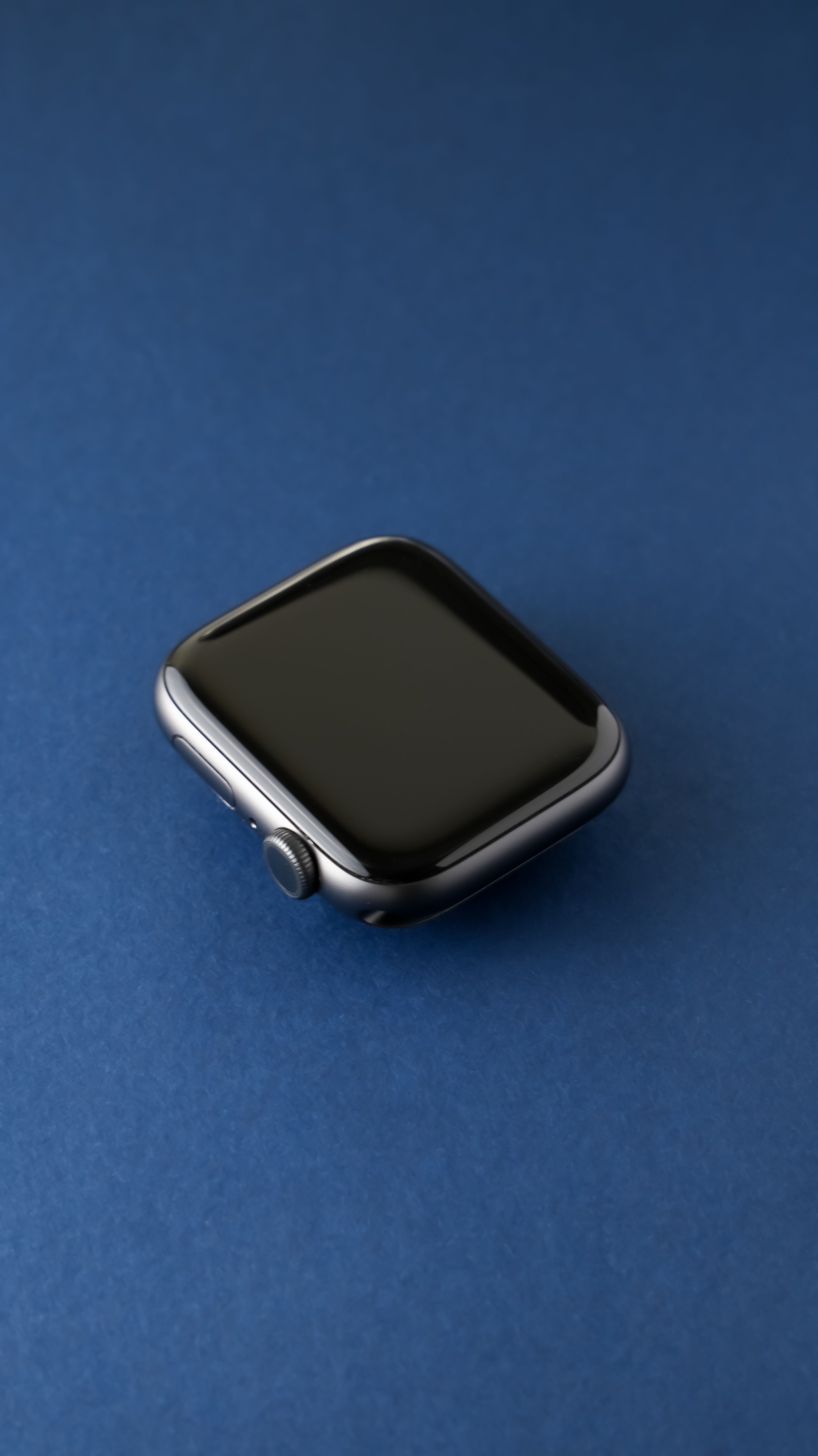
Wearable Device Strap Buckle Family
A wearable hardware company produces six watch body sizes, five strap widths, and four colors per size. The entire matrix would require more than 30 injection molds, and color inventory alone would make the business model unfeasible. This team printed the buckle body using SLS PA11 and dyed each batch individually. PA11 was chosen over PA12 because the buckle is latched and unlatched hundreds of times daily—PA12's ductility would cause it to break within a year. Vapor smoothing seals the near-surface pores, preventing sweat and sunscreen from seeping in and keeping the aesthetic color stable. Each size × color combination runs in batches of 200–800 units, shipped directly from CAD, with a lead time of five to seven days, compared to eight to twelve weeks for injection molding batches.
Key design action: The cantilever clip is 1.3 mm thick and has a 9 mm engagement length—a ratio greater than 7:1, which is within PA11's fatigue range but exceeds PA12's survival range. Each clip also features a 0.4 mm return stop on the first layer to ensure that excessive force during installation is applied to a rigid feature, rather than crushing the cantilever.
Drone Frame Bracket with Cooling Channels
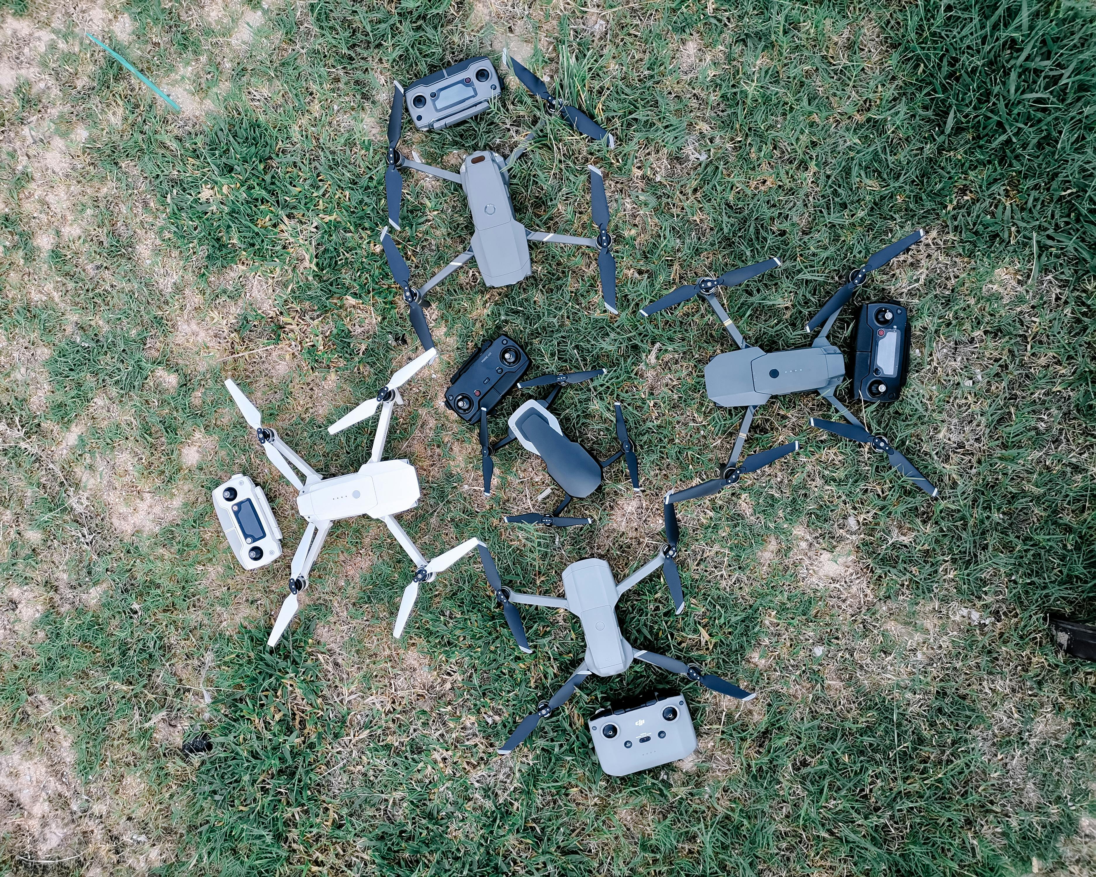
On a medium-sized commercial drone, the ESC (electronic speed controller) bracket also serves as an airflow channel, keeping the ESC surface temperature approximately 15°C lower than patch-type cooling solutions. This part is printed with glass-filled PA12 for rigidity and heat resistance; the interior uses a lattice infill, with fewer walls but retaining torsional rigidity. SLS excels here not just because it's fast—but because the integrated airflow geometry cannot be injection molded as a single piece, and splitting it into multiple components would increase weight and compromise the cooling path. The part is only bead blasted for shipping; internal structural components do not require aesthetic treatment.
Chemical Processing Nozzle
A laboratory automation supplier needed a nozzle that would daily contact ethanol, isopropanol, and dilute acids, while also undergoing hundreds of repeated flexes each day at the spring seat. SLS polypropylene was chosen as the material—PA12 would swell slightly after repeated contact with IPA and crack at the spring seat within a few months. PP's tensile strength is only two-thirds that of PA12, which was compensated in the design with a 2.2 mm wall thickness (PA12 would be 1.5 mm). The surface was only bead blasted—because chemical contact does not allow for dyed surfaces. The project produces 150 units per month, with four variations, well below the break-even point for any injection molding, placing it squarely in SLS's sweet spot.
Do / Don't Checklist
| Do | Don't |
|---|---|
| Select family based on dominant load type first | Pick material solely based on tensile strength |
| Use PA11 for features with repeated flexing | Use PA12 for high-cycle living hinges |
| Add powder removal holes to every internal cavity | Ship sealed hollow parts—they will leak powder for months |
| Allocate time for bead blasting for every part | Assume out-of-machine surface is ready for delivery |
| Dye white powder parts for uniform coloring | Dye aesthetic surfaces that will be scratched |
| Vapor smooth all sealing or contact surfaces | Skip sealing for parts that contact skin or sweat |
| Adjust clearances for post-processing (0.5 mm for dyeing, 0.6 mm for painting) | Use the same clearance for all post-processing routes |
Common Mistakes and How to Avoid Them
| Mistake | Why it Fails | How to Avoid |
|---|---|---|
| Choosing glass-filled PA12 for snap-fits | Glass fibers reduce elongation to below 6%; thin beams break on first flex | |
| Designing to minimum wall thickness without considering bed position | Large flat plates warp at bed edges | Place thin plates in the center of the bed; add ribs for long spans |
| Not designing powder removal holes | Residual powder adds weight, slowly leaks, and fails sealing tests | Two 4 mm holes for every enclosed volume—one in, one out |
| Treating dyeing as painting | Scratches expose white base material; dye penetrates only about 0.4 mm deep | For aesthetic surfaces that will be scratched, use primer + spray paint |
| Assuming SLS and MJF are interchangeable | Significant differences in color, density, and dyeing response | Choose based on aesthetic and material requirements, not just quotes |
Material Selection Checklist
Run through this checklist before officially selecting a material family and printing the first part.
- Dominant load type confirmed: rigid, ductile, or flexible?
- Temperature and chemical exposure windows documented on drawings
- Cycle count for active features estimated (specify PA11 for > 10,000 cycles)
- Powder removal path for every enclosed cavity reviewed
- Bed placement planned for large areas or precision features
- Post-processing route determined (blasting / vapor / dyeing / painting / coating), and clearances adjusted accordingly
- First article inspection scheduled after final post-processing, not straight out of the machine
- If still deciding between SLS vs. MJF, make aesthetic decisions before getting quotes
Design Highlights
SLS is not a single-material process. Correct results come from matching the material family to the dominant load type—PA12 for general engineering, PA11 for flexing, GF for rigid structures, PP for chemical contact, TPU for flexible interfaces—and then coupling it with a post-processing route suitable for the surface application. If SLS vs. MJF is still in question, the deciding factor is usually color and aesthetics, not mechanical performance. Spending time on the right decisions in the early stages (material and post-processing selection) is the most cost-effective way to avoid re-issuing production orders due to "wrong material choice" mid-production.


0 comments