
A product team delivered an articulated prototype arm with 18 hinges as a single SLS print, fully functional right out of the powder bed – no screws, no bushings, no assembly steps, and no line-side kitting. This isn't manufacturing magic, but the payoff for designing specifically for powder bed fusion. The same geometry, if done by FDM or SLA, would result in 18 prints, 36 support removal operations, and a pile of fragile pins.
Designing for SLS is not the same as general additive design. Unfused powder itself acts as support, enclosed volumes pose powder removal problems, and the feature's position in the powder bed subtly changes its dimensional behavior. These rules aren't derived from generic DfAM slides, but from the real physics of how nylon melts, cools, and is subsequently excavated.
Why DfSLS is a distinct design discipline
Most DfAM guidelines start by assuming the process needs supports, bottom surfaces degrade, and part orientation is primarily to reduce supports. SLS flips all three of these premises: powder supports everything, every surface is considered a top surface, and orientation focuses on accuracy and thermal history, rather than support cost.
If you've already decided which polymer to use for SLS (PA12, PA11, glass-filled, PP, TPU), please refer to the companion article "SLS Material Family." This article assumes the material is finalized and focuses solely on geometry, orientation, part consolidation, and the detailed limits you can truly specify on a drawing.
SLS Manufacturability Reference Figures
The table below is a single-page version our team has pinned above the design review screen. The figures are based on well-calibrated industrial machines, PA12, and layer thicknesses of 0.10–0.12 mm; glass-filled and TPU versions will push some detailed items outwards.
| Feature | Minimum Value | Stable Value | Notes |
|---|---|---|---|
| Unsupported Wall Thickness | 0.7 mm | 1.0 mm | Below 0.7 mm prone to warping or tearing during powder removal |
| Supported Wall / Rib | 0.4 mm | 0.6 mm | Must connect back to the main body at both ends |
| Embossed Text / Line | 0.5 mm width × 0.5 mm height | 0.8 × 0.8 mm | Debossed text is usually more readable than embossed |
| Through-hole Diameter | 1.5 mm | 2.0 mm | Hole diameter typically shrinks by 0.1–0.2 mm |
| Powder Removal Hole for Enclosed Spaces | 4.0 mm | 5.0 mm | At least one per cavity, ideally diagonally placed |
| Clearance for Moving Parts | 0.4 mm | 0.5 mm | Print-in-place hinges, linkages, joints |
| Living Hinge Beam Thickness | 0.4 mm | 0.5 mm | Combine with 2–3 mm span to improve fatigue life |
| Lattice Strut Diameter | 0.6 mm | 0.8 mm | Below 0.6 mm prone to collapsing during powder removal |
| Hole to Edge Distance | 1.0 mm | 1.5 mm | Measured from wall to nearest hole edge |
Orientation and Powder Bed Position
SLS parts are not truly isotropic. Tensile strength along the layers is typically 10–15% lower than in-plane, holes built with their axis along Z will be oval-shaped, and surfaces built vertically will show layer lines that sandblasting cannot completely eliminate. Orientation is not just for factory convenience; it's a design decision.
| Feature | Optimal Orientation | Avoid | Reason |
|---|---|---|---|
| Precision Round Hole | Axis in the plane (X or Y) | Axis along Z | Layer shifting can make holes oval |
| Aesthetic Surface | Slanted 10–20° from horizontal | Perfectly vertical | Vertical surfaces show layer lines |
| Long, Thin Beam | Flat orientation, long axis in XY | Z-cantilever | Z-cantilevers can thermally sag |
| Snap Fit / Hook End | Tip pointing upwards | Tip pointing downwards | Downward tips accumulate sintered fluff |
| Text on Surface | Surface slanted 10° from vertical | Surface flat against Z-top | Debossed text is generally more legible |
| Dimensionally Critical Part | Center of powder bed, mid-height | Edge of powder bed or top layer | Edge cooling can cause drift of ±0.3% |
For tolerance-critical parts, we specify the desired build region on the drawing: center of the powder bed, mid-height, and along the reference axis plane. This note costs nothing but eliminates one of the most common reasons for first-article rejection.
Consolidating Multi-Part Assemblies into a Single Print
SLS shows its greatest value when sub-assemblies that were previously bolted or bonded can be redesigned as a single piece. The economics work out when the benefits of reduced part count outweigh the cost of nylon volume. Here are four questions we ask before deciding to consolidate.
| Scenario | Consolidate? | Conditions |
|---|---|---|
| Annual demand ≤ 50, 5+ parts | Yes | Part count and assembly labor dominate |
| Annual demand 500, 3 parts | Case by case | Compare nylon volume to injection mold amortization |
| Mechanism, 3+ joints | Yes | Print-in-place can completely eliminate assembly |
| High cycle load path | No | Layer-wise fatigue may be lower than bolted assembly |
| Requires metal threaded inserts | Partial consolidation | Consolidate the main body, retain heat-set inserts |
| Internal channels, manifolds | Yes | SLS eliminates cross-drilling and plugging |
Print-in-Place Mechanisms — Powder is the Support
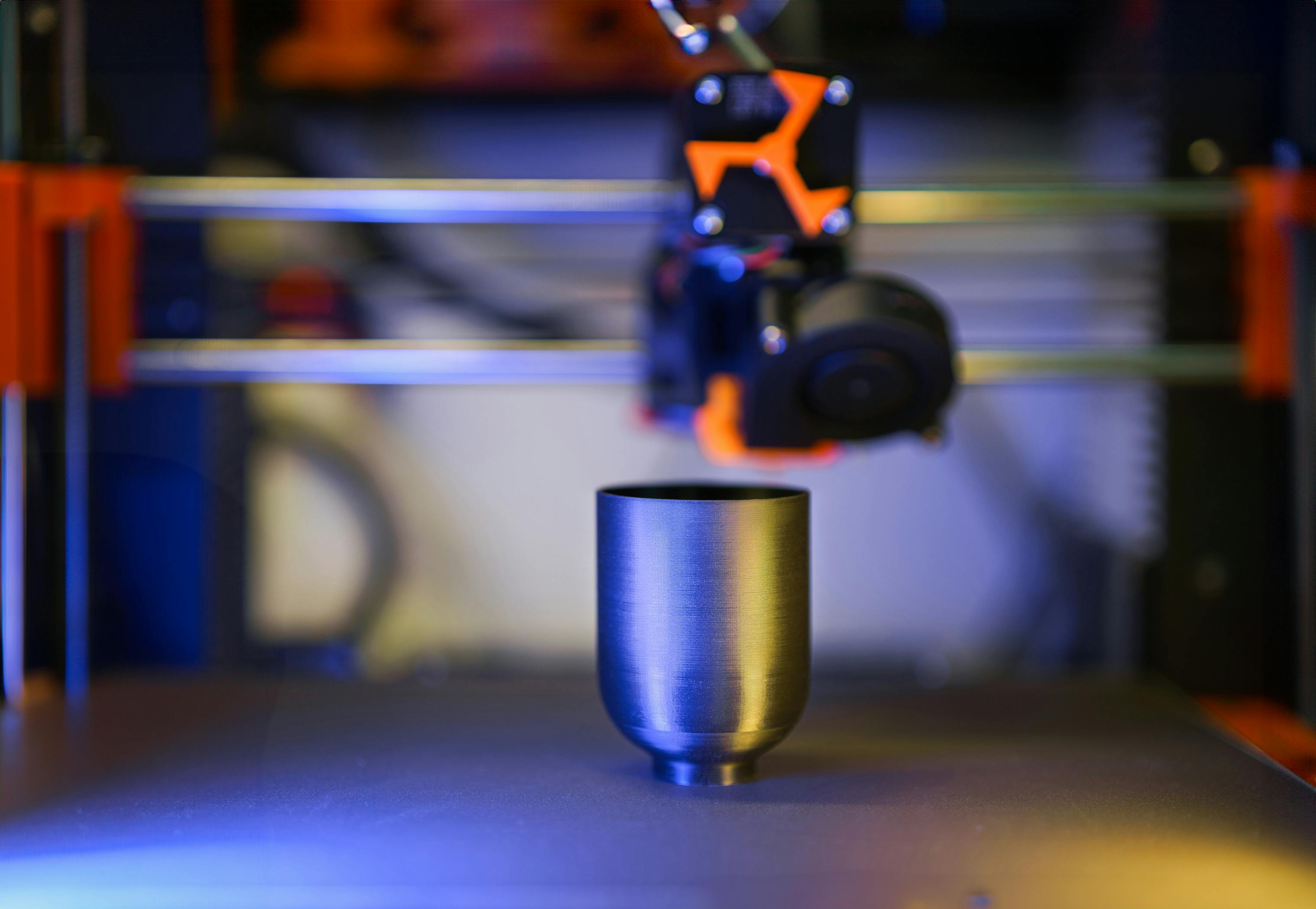
The design rules for print-in-place joints are simple: maintain at least 0.4 mm clearance for each sliding or rotating surface, and ensure there's an exit path for powder within that clearance. A nominal clearance of 0.5 mm leaves enough margin for dimensional drift and allows for smooth operation after sandblasting.
Stop features, snap edges, and pin heads, which prevent disengagement, must also have a path for powder removal. A common mistake is designing pin heads without a powder removal channel: the joint prints fine, but can't be cleaned, and the mechanism is seized upon receipt. Adding a ≥ 4 mm drain hole usually solves this.
Define Post-Processing Before Powder Removal
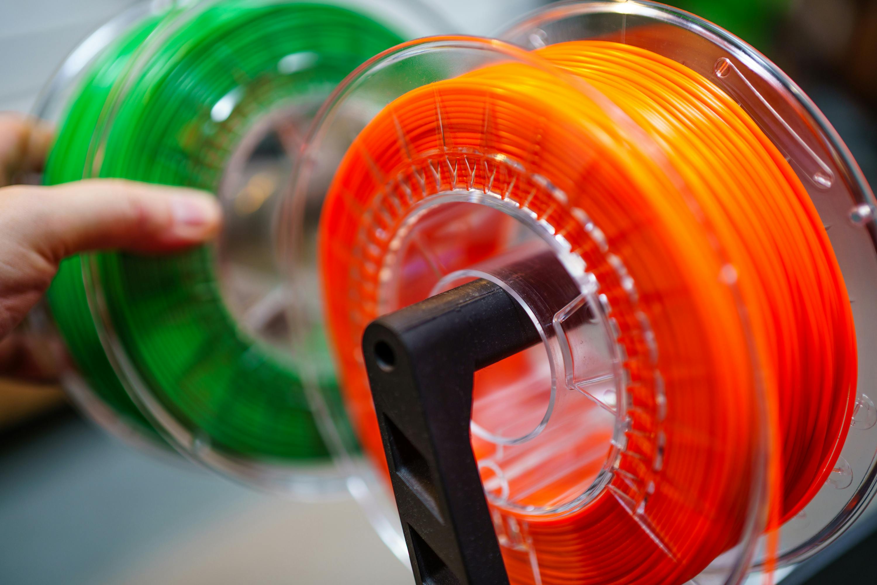
Post-processing decisions must be finalized before parts enter the powder removal station, as each post-processing route consumes a different amount of surface material. Raw parts are about Ra 8–12 µm, sandblasted parts are about Ra 6–8 µm, and vapor smoothed parts can be below Ra 2 µm, but each route has its own tolerance implications (see vapor smoothing section). The clearances reserved during design must be determined based on the final post-processed state, not the raw part.
Applications — Three Cases Only Possible with SLS
Articulated Prototype Arm with 18 Print-in-Place Joints
A robotics lab needed a display arm that could be posed for exhibitions. The traditional approach would involve 18 machined aluminum joints, 36 bushings, and assembly jigs. The SLS approach involved one CAD file, 0.45 mm joint clearance, one powder bed print, and hinges that were directly in place – reducing lead time from 3 weeks to 4 days, and part count from 54 to 1.
Consolidated Pneumatic Manifold Replacing a 12-Part Sub-Assembly
An automation integrator previously used a 12-part aluminum manifold (body, end caps, cross-drilled channels, brass plugs), requiring two hours for assembly and leak testing. Redesigning it as a single SLS PA12 part allowed for 3D internal channels instead of linear drilled holes, and optimized the bend radius at connections from 2 mm to 4 mm to reduce flow resistance. The result was a 38% weight saving and assembly time reduced from 2 hours to 8 minutes.
Medical Training Aid with Integrated Hinges
A surgical trainer manufacturer needed a disposable anatomical insert that could open like a book to reveal internal structures. Injection molding would require two molds plus pin hinges. SLS PA12 (properly dyed for biocompatibility) allowed the hinges, two body halves, and color-separated chambers to be printed in a single run. The cost per piece was reduced to 35% of the molded solution, and revisions could be implemented in just 48 hours.
Dos and Don'ts
| Do | Don't |
|---|---|
| Add ≥ 4 mm powder removal holes to every enclosed space | Leave decorative enclosed cavities sealed |
| Reserve the central powder bed area for tolerance-critical parts | Let the factory place critical parts at the edge of the powder bed |
| Use 0.4–0.5 mm clearance for print-in-place joints | Apply FDM's 0.2 mm clearance to SLS |
| Use debossed text instead of embossed text | Use 0.3 mm embossed text and expect it to survive sandblasting |
| Orient layers away from the axis of circular holes | Print Ø2 mm holes with their axis along Z |
| Add ribs to surfaces over 80 mm | Leave a 150 × 2 mm flat plate and expect it not to warp |
Common Mistakes
Failure modes in customer-submitted SLS files tend to concentrate in five areas: enclosed internal volumes, print-in-place clearances ported from FDM, embossed text too thin to survive sandblasting, critical holes with their axis along Z, and thin flat plates over 80 mm without support. Each of these has a corresponding design action in this article.
A more subtle mistake is treating "no supports needed" as "no orientation decisions needed." Orientation still dictates accuracy, appearance, and anisotropy. Leaving orientation entirely to the factory is like leaving mold gate placement entirely to the injection molder — it works most of the time, until it doesn't.
Pre-Build Checklist
- Each enclosed space has at least one ≥ 4 mm powder removal hole.
- Print-in-place clearance is set to 0.4–0.5 mm, not FDM's 0.2 mm.
- Tolerance-critical features are annotated for central powder bed, mid-height placement.
- The axis of tight-fitting circular holes is in the plane, not along Z.
- Text is debossed, with width ≥ 0.5 mm and depth ≥ 0.5 mm.
- Surfaces exceeding 80 mm have at least one reinforcing rib.
- Post-processing route (sandblasting / smoothing / dyeing) is specified for correct surface loss allowance.
- Material selection has been confirmed against the companion article "SLS Material Family."
Design Conclusion
The core of DfSLS is exchanging "support-free freedom" for a new set of constraints: powder removal holes, powder bed thermal zones, print-in-place clearances, and orientation-driven accuracy. Teams that internalize these four constraints will stop seeing SLS as "3D printing with slightly better appearance than FDM" and instead turn it into a process truly capable of consolidating complex mechanisms and eliminating assembly costs.
Pairing this design thinking with the correct polymer selection closes the loop. The companion article "SLS Material Family" covers the choice of PA12 / PA11 / PA12-GF / PP / TPU; this article addresses the geometric rules that remain constant regardless of which nylon is chosen.


0 comments