
The first SLA print failure usually stems from one of four things: wall thickness below 0.5 mm warping under peel force, a hollow part lacking a 3 mm drain hole trapping a cupful of uncured resin, a 25-degree overhang angle sagging under its own weight, or post-curing shrinking the part by 0.3% to 0.6% along its longest axis. These are not uncommon scenarios; they occur in about half of the initial SLA cases we review, and all are design choices made before the file even enters the slicer.
This article focuses on "Designing for SLA": a process where lasers or LCDs cure liquid resin, and whose yield rate is primarily governed by support, orientation, drainage, and post-cure thermal behavior. We will not reiterate the comparison of resins for SLA, DLP, and PolyJet – that topic is covered in detail in "Resin 3D Printing."
Why SLA Design Differs from FDM Design
FDM is an extrusion process: gravity, span, and Z-seams are the primary limitations. SLA is a peel process: each layer must be pulled from the release film or the bottom of the vat, and the peel force is proportional to the exposed cross-sectional area of that layer. Thin walls with large cross-sectional areas encountering large peel forces are the starting point for warping and delamination.
The inference is: SLA design cannot be decided separately from orientation. You cannot finalize feature specifications without knowing how the part will be oriented in the vat, because orientation changes which surfaces will bear support scars, which cavities will accumulate liquid, and in which direction post-cure shrinkage will accumulate.
SLA-Specific DFM Constraints
The following values apply to desktop/benchtop SLA systems using 50 to 100 micron laser spots or pixels and printing general engineering resins, serving as conservative defaults. Tough, flexible, and high-temperature resins will have different modified values.
| Feature | Minimum Value | Recommended Value | Failure Reason Below Minimum |
|---|---|---|---|
| Unsupported Wall | 0.5 mm | 0.8 to 1.2 mm | Peel force tears wall from supports |
| Supported Wall | 0.4 mm | 0.6 mm | Shaking during recoating, printing ripples |
| Through-hole Diameter | 0.5 mm (vertical) | 1.0 mm | Uncured resin clogs hole, sealed during post-cure |
| Embossed Text Height | 0.4 mm | 0.6 mm | Printable but loses clarity after post-cure expansion |
| Engraved Text Depth | 0.4 mm | 0.6 mm | Resin accumulates in grooves, filled during post-cure |
| Unsupported Overhang | 30 degrees from vertical | 45 degrees | Sags under its own weight before next layer is secured |
| Unsupported Span | 1.0 mm | Avoid, add support | Sags over 0.2 mm, prints as a concave curve |
| Hollow Part Drain Hole | 3.0 mm | 4 to 5 mm | Trapped resin seals during post-cure, shell deforms |
Support Design and Orientation Trade-offs
SLA supports have four tasks: resisting peel forces to anchor the part, preventing overhangs from sagging, dissipating local heat during curing, and determining which surface will have cosmetic scars. Contact density is the most frequently adjusted single parameter, but it changes not only scars but also pull-off strength.
| Support Strategy | Contact Density | Surface Cost | Applicable Scenarios |
|---|---|---|---|
| Lightweight Aesthetic | 0.4 mm tip, sparse | Low; can be sanded and re-cured to remove scars | Display pieces, jewelry master patterns, lens mounts |
| Standard Engineering | 0.6 mm tip, medium | Medium; visible scars but can be filled | Functional jigs, manifolds |
| Heavy-Duty / Tall Part | 0.8 mm tip, dense | High; requires rework or hiding that surface | Parts over 100 mm tall, high-density resin |
| Internal Lattice Support | System generated branches | Traces left on hidden surfaces | Cantilevers, architectural overhangs |
| Hand-drawn Raft Ribs | User-drawn | Design built-in features | Lost wax parts, core patterns |
Orientation is a tug-of-war between peel force, support coverage, and Z-axis dimensional error. Lying flat shortens Z-height (faster printing), but peel force is highest, and planar surfaces are prone to delamination bands. Standing upright reduces peel force but multiplies Z-height, with the worst dimensional error accumulating along the longest dimension. Most engineering parts compromise with a 15 to 30-degree tilt.
Drainage Strategy for Hollow Parts
Hollowing out parts to save resin is common practice, but a sealed hollow is a trap. Uncured resin inside a closed shell does not lose its photoreactivity; during post-curing, UV passing through thin walls will partially cure the trapped resin pool, causing the shell to locally swell inwards and deform, or crack days later. The solution is always to open at least two holes: an inlet for IPA rinse to flow through, and a vent for air to escape.
| Hollow Volume | Single Drain Hole | Inlet + Vent Double Hole | Remarks |
|---|---|---|---|
| < 5 cm3 | 3 mm | Optional | Can be drained by centrifugal force or shaking |
| 5 to 30 cm3 | 4 mm | Recommended 3 mm + 3 mm | Rinse with IPA through inlet |
| 30 to 100 cm3 | 5 mm | Must be 4 mm + 4 mm | Consider using negative pressure |
| > 100 cm3 | 6 mm | Must be 5 mm + 5 mm | Consider dividing and then bonding |
Designing for Post-Cure Dimensional Changes
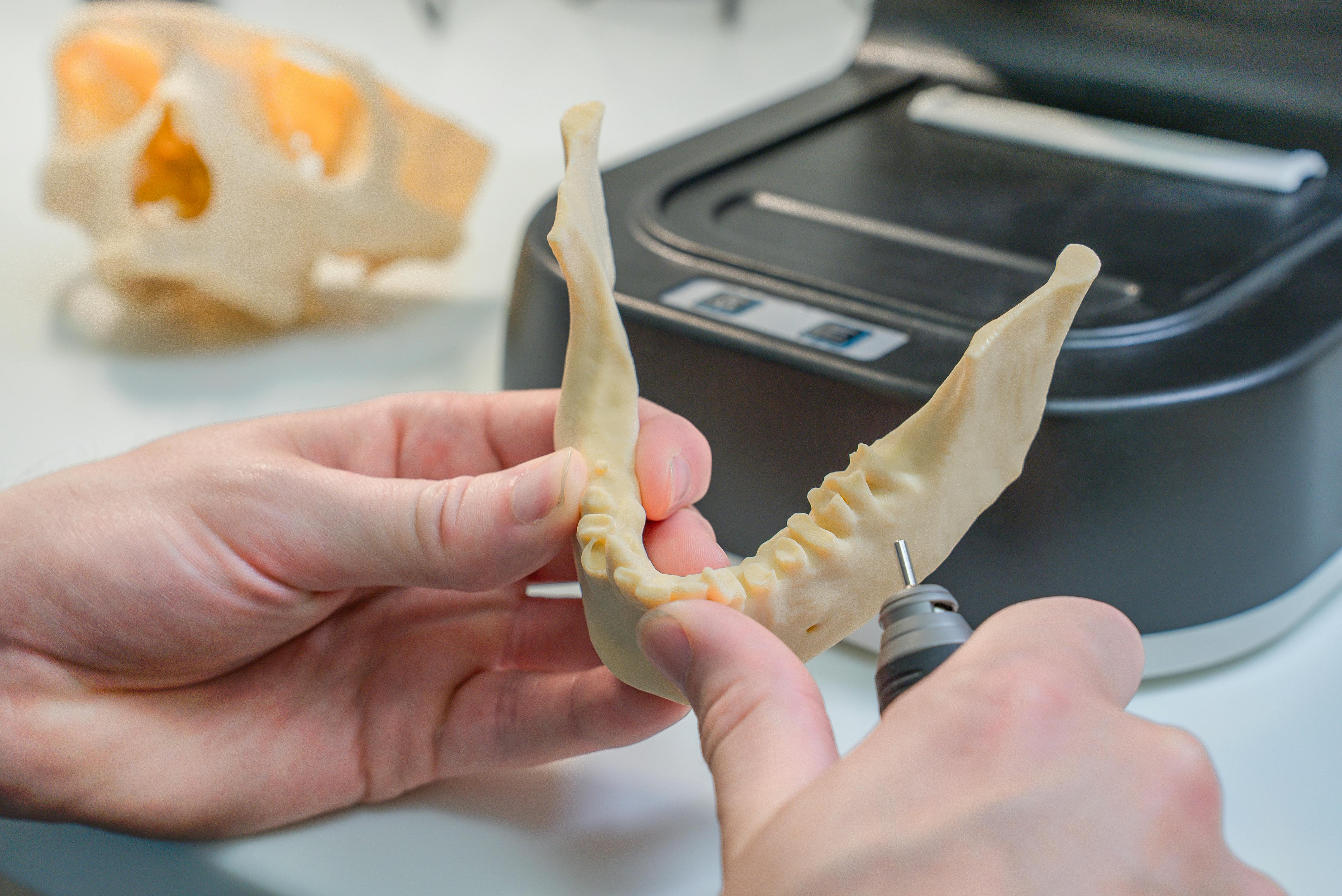
"Green parts" removed from the SLA platform are 80% to 95% cured, with residual curing occurring in a 40 to 60-degree UV post-curing chamber, where the part will shrink. General engineering resins experience about 0.3% to 0.6% linear shrinkage during post-curing, with high-temperature resins reaching up to 0.8%; the longest dimension is most affected.
Holes shrink inwards, bosses shrink outwards, and slot widths shrink towards the center line. If the part has press-fit metal pinholes, enlarge the hole diameter by 0.4% according to the print orientation; if it's an external mating boss, reduce it by 0.4%. Mass effect is also important: in parts with significant wall thickness differences, thicker areas shrink slower, and thinner areas shrink faster, which can cause large flat plates to warp.
Treating Resin Selection as a Design Decision
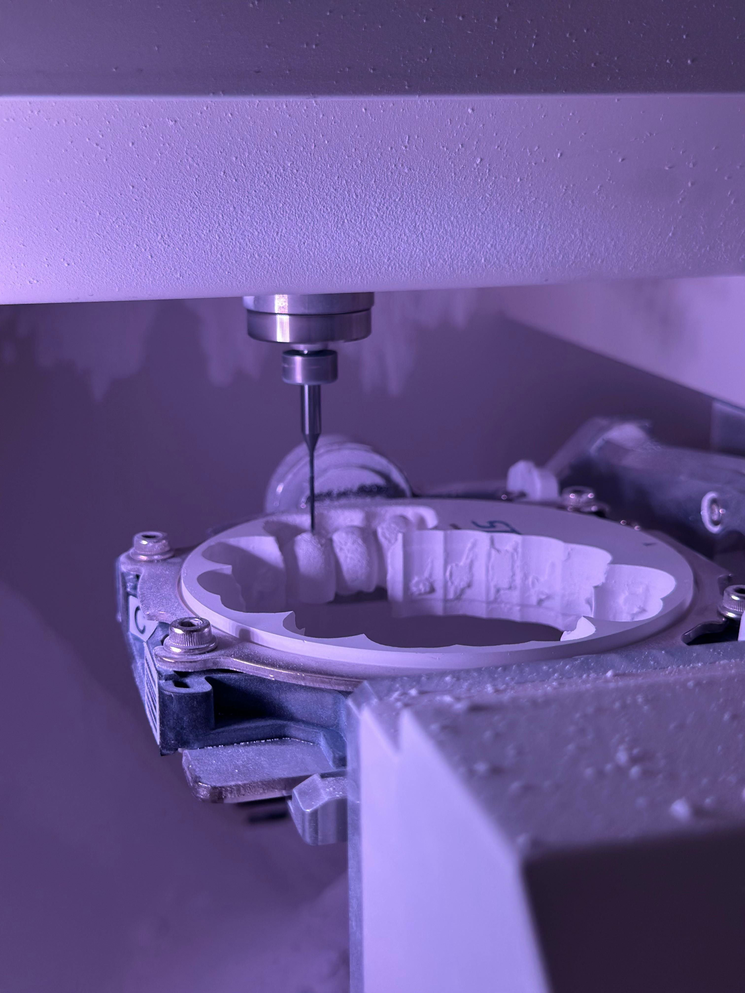
We won't rehash the resin family comparisons from the "Resin 3D Printing" article, but the design implications are worth discussing separately. Tough and durable resins require walls 30% thicker than standard resins. Flexible resins cannot support thin overhangs. Lost-wax casting resins have low ash content, and support residue must be handled more carefully in design as they are not suitable for extensive post-machining. High-temperature resins require longer post-curing and exhibit greater shrinkage—longer thermal exposure times must be accounted for when designing tolerances.
Applications: Three SLA-First Design Cases
Lost-Wax Casting Master for a Signet Ring
A jeweler wants to cast a 14 mm 18k gold signet ring. The ring face requires 50-micron text, and the shoulder wall thickness is only 0.6 mm. SLA design choice: tilt the ring face 30 degrees so the engraving faces upwards for unsupported printing, and the shoulder walls are peeled sideways rather than frontally, allowing the 0.6 mm wall to print without warping. Using lost-wax casting resin, the entire piece is designed as a thin shell with minimal raft ribs to allow gas to escape during casting.
Lens Mount for a Prototype Camera
A camera prototype requires a four-element lens barrel, including two M30 x 0.5 threads and internal flange tolerances of ±0.05 mm. The lens barrel is printed vertically, allowing the threads to form in the X-Y plane with minimal dimensional error, and the flange surface faces upwards to ensure flatness with minimal Z-error. After post-curing, an M30 tap is used to clear 0.1 mm of post-cure growth.
1:200 Scale Architectural Cantilever Model
A 1:200 scale architectural cantilever roof model, with a print length of 60 mm, requires a seamless appearance and no print sagging. The cantilever is oriented along the Z-axis at a 25-degree angle from vertical, allowing the underside to be accessed by internal tree-like supports, contacting only 14 0.4 mm tips; after post-curing, lightly sand with 2000 grit sandpaper, and the scars disappear at a 1:200 scale.
Do's and Don'ts
| Do | Don't |
|---|---|
| Decide orientation before locking dimensions | Throw CAD directly into the slicer and let it decide orientation |
| Open at least one 3 mm drain hole for each hollow | Seal hollows for aesthetics |
| Enlarge holes by 0.3% to 0.6% in the print direction | Print press-fit holes with nominal CAD dimensions, expecting perfect post-cure fit |
| Deliberately hide support scars on a designated B-surface | Print the most important aesthetic surface facing down on the build platform |
| Select resin family before setting wall thickness | Design with standard resin, then switch to tough or flexible resin afterwards |
| Orient thin walls at 15 to 30 degrees from vertical | Print thin walls completely flat on the platform |
Common Error Reference Table
| Error | Symptom | Correction |
|---|---|---|
| Wall thickness below 0.5 mm and lying flat | Delamination bands, surface ripples | Tilt 20 degrees, thicken to 0.8 mm |
| Sealed hollow | Post-cure shell cracking | Add 4 mm inlet + 3 mm vent |
| Press-fit holes with nominal dimensions | Pin cannot be pressed in after post-cure | Enlarge hole diameter by 0.4% |
| Engraved text 0.2 mm deep | Text filled in and disappears | Deepen to 0.6 mm |
| Cantilever at 20 degrees from vertical | Underside sags, stair-stepping | Add supports or rotate to 35 degrees |
| No B-surface marked | Support scars on visible surfaces | Mark B-surface during slicing and orient towards platform |
Please use this checklist as a final gate before exporting the STL. Most teams print it and stick it next to the machine; we've also seen it written directly as slicer pre-check comments, appearing in print reports alongside orientation screenshots.
Pre-Print Checklist
- Orientation locked and B-surface marked before slicing
- All unsupported walls are 0.5 mm or more in the print direction
- Each hollow has 3 to 6 mm drain holes depending on volume
- Overhang angles are greater than 30 degrees from vertical, or supports have been added
- Hole diameters compensated for post-cure shrinkage along the print axis
- Embossed/engraved text has at least 0.4 mm relief or depth
- Resin family selected and wall thickness adjusted accordingly
- Support contact density matches surface grade (aesthetic/functional)
Design Takeaways
SLA rewards designers who treat orientation, drainage, and post-curing as upstream design inputs rather than downstream slicing settings. The biggest yield improvements we've seen often come from locking in orientation before defining feature dimensions and pre-planning cleaning paths for every hollow.
If the values in this article conflict with your resin supplier's datasheet, please defer to the datasheet – suppliers have a more precise understanding of their material properties than general guidelines. The purpose of this article is to inform you what numbers to check and where they might cause issues.


0 comments