
A 12 mm inner diameter of an aluminum bearing housing returned at 12.052 mm, exceeding the ±0.025 mm specification by 0.027 mm. Bearings slipped under load, the gantry chattered, and a four-week prototyping cycle restarted—all because a tolerance was tighter than what the process could economically achieve.
CNC tolerance is not a single number arbitrarily written on a drawing, but a negotiation between feature size, machine capability, material behavior, measurement methods, and unit cost. This guide covers ISO 2768 default grades, achievable tolerances for various processes, cost multiplier curves, GD&T fundamentals, and how aluminum, steel, titanium, and plastics individually shift the window of achievable tolerances.
Read this once before filling in the title block next time: Most parts are perfectly functional with ISO 2768-m, and features truly requiring ±0.01 mm are typically fewer than five per drawing.
ISO 2768 General Tolerance Grades
ISO 2768-1 specifies general tolerances for linear and angular dimensions not individually indicated. Choosing the correct default grade can simplify drawings and make manufacturing smoother.
| Nominal Size (mm) | f (Fine) | m (Medium) | c (Coarse) | v (Very Coarse) |
|---|---|---|---|---|
| 0.5–3 | ±0.05 | ±0.10 | ±0.20 | — |
| 3–6 | ±0.05 | ±0.10 | ±0.30 | ±0.50 |
| 6–30 | ±0.10 | ±0.20 | ±0.50 | ±1.00 |
| 30–120 | ±0.15 | ±0.30 | ±0.80 | ±1.50 |
| 120–400 | ±0.20 | ±0.50 | ±1.20 | ±2.50 |
| 400–1000 | ±0.30 | ±0.80 | ±2.00 | ±4.00 |
Key design action: Default to 2768-m in the title block, and only reserve 2768-f or tighter for fits, datums, and sealing surfaces—tightening tolerances elsewhere only increases inspection time without functional returns.
Achievable Tolerances by Process
Capability is not a number from a machine catalog, but the level your machine shop can consistently reproduce for a 200-piece batch using their fixtures, programs, and operators.
| Process | Typical (mm) | Strict (mm) | Extreme (mm) | Notes |
|---|---|---|---|---|
| 3-axis milling | ±0.05 | ±0.025 | ±0.010 | Limited by tool changes/setups |
| 5-axis milling | ±0.025 | ±0.013 | ±0.008 | Single setup, reduces datum transfer errors |
| CNC turning | ±0.025 | ±0.013 | ±0.005 | Best radially |
| Surface grinding | ±0.005 | ±0.003 | ±0.001 | Flatness/Parallelism |
| Wire EDM | ±0.013 | ±0.005 | ±0.002 | Hard materials, sharp corners |
Tolerance Grade to Cost Multiplier
| Grade | Example | Cost Multiplier | Cost Source |
|---|---|---|---|
| Coarse (2768-c) | ±0.20 mm / 30–120 | 1.0× | Single operation, minimal QC |
| Medium (2768-m) | ±0.10 mm / 30–120 | 1.3× | Default tooling, sampling QC |
| Fine (2768-f) | ±0.05 mm / 30–120 | 2.0× | Tool compensation, 100% inspection |
| Precision Grade | ±0.013 mm | 4–6× | Grinding/EDM, controlled environment |
| Ultra-Precision | ±0.005 mm | 6–8× and above | CMM 100% inspection, jig grinding |
Material Impact on Achievable Tolerances
| Material | Stable Tolerance | Risk | Countermeasure |
|---|---|---|---|
| Aluminum 6061 | ±0.013 mm | Thermal expansion | Adequate cooling, dwell time |
| Low carbon steel | ±0.025 mm | Tool wear | Carbide tools, in-process measurement |
| Stainless steel 316 | ±0.025 mm | Work hardening | Sharp tools, single pass |
| Titanium Ti-6Al-4V | ±0.05 mm | Springback, heat | Rigid clamping, low cutting speed |
| POM / PEEK | ±0.05 mm | Creep, moisture absorption | Temperature/humidity control before measurement |
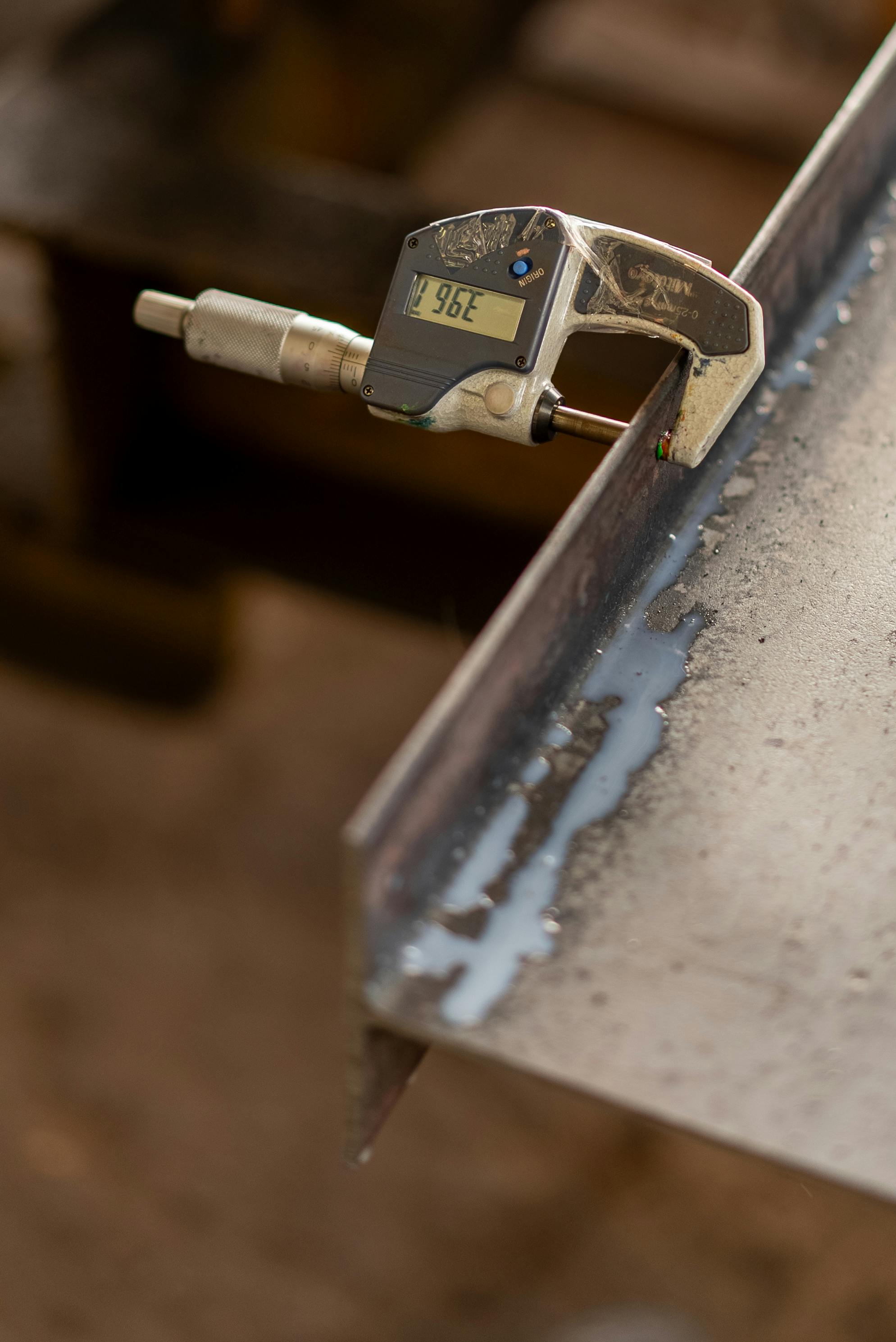
Plastics continue to deform after machining and require several hours at controlled temperature in the measurement lab before CMM. Titanium alloys spring back after heavy cuts; finishing passes require shallow depths of cut and sharp tools.
Tolerance Stack-up and GD&T Fundamentals
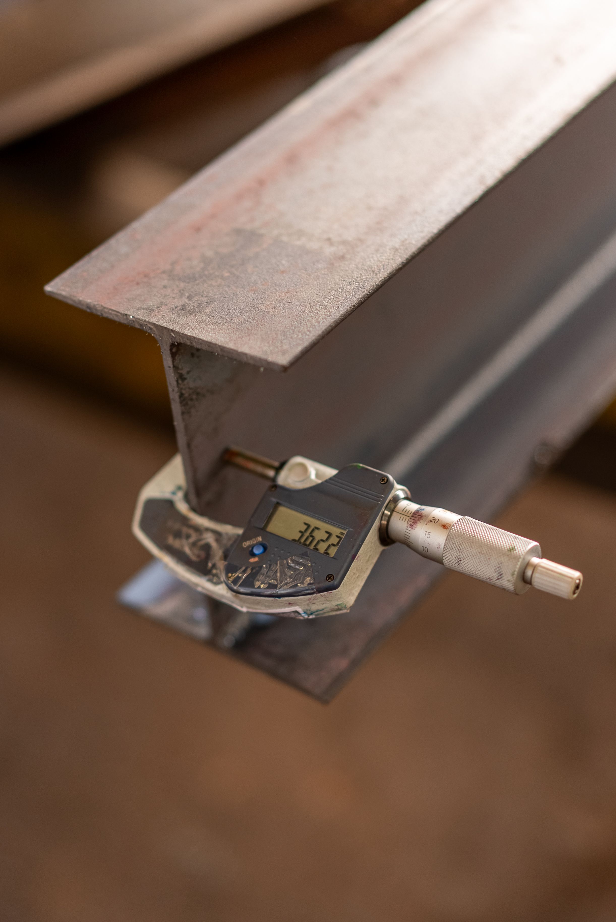
Three features in series, each with ±0.05 mm, would stack up to ±0.15 mm in the worst case. GD&T allows you to allocate tolerance budget where functionality matters—position, perpendicularity, profile—instead of dimensioning each direction separately. At least three datums (A primary, B secondary, C tertiary) are needed to fully define a part's spatial orientation.
Use position tolerance with MMC for bolted joints (additional tolerance gained when the hole is larger), profile for sealing surfaces, and runout for rotating shafts. Always declare a primary/secondary/tertiary datum system consistent with the actual assembly method.
Application Scenarios: Tolerance Choice Determines Cost
Robot Gearbox Housing
Bearing hole H7 (approx. +0.021/0 mm for 30 mm) is the primary cost driver. Changing the entire drawing from ±0.025 mm to only two bearing housings with H7, and the rest to 2768-m, reduced the quote by 38% with no loss of function.
Optical Substrate
Flatness of 0.01 mm over 200 mm must be achieved by grinding after milling. Split the process into milling a blank and then grinding the top surface, while the remaining geometry is completed on a 3-axis mill at standard cost.
Medical Device Turning Shaft
Diameter ±0.005 mm and Ra 0.4 µm are achieved in a single setup on a Swiss-type lathe. If split into milling and turning, the stacked error from re-clamping cannot be recovered by any inspection plan.
Recommendations / Avoidances
| Recommend | Avoid |
|---|---|
| Default ISO 2768-m in title block | Uniform ±0.025 mm across the entire drawing |
| Tighten tolerances only on functional features | Tighten tolerances on aesthetic edges and chamfers |
| Annotate GD&T with clear datums | Mix linear and GD&T for the same feature |
| Specify surface roughness on critical surfaces | Do not specify Ra for sealing surfaces |
| Discuss capabilities with machine shop early in design | Assume any shop can achieve ±0.01 mm |
Common Mistakes
| Mistake | Consequence | Correction |
|---|---|---|
| Entire drawing ±0.01 mm | 2–4x cost, longer lead time | Specify tolerances per feature |
| Undefined datum system | Inspector chooses datums arbitrarily | Clearly define A/B/C datums |
| Tight tolerances on plastics | Deformation after machining | Loosen to ±0.05 mm and control temperature |
| Hole position without MMC | Wasted tolerance budget | Add Ⓜ modifier |
| No surface roughness specified | Inconsistent fit quality | Specify Ra on critical surfaces |
| Ignoring tolerance stack-up | Worst-case functional failure | Perform RSS and worst-case analysis |
Checklist Before Releasing Drawing
Run through this checklist before the drawing leaves the engineering department to catch 80% of tolerance-related quoting disputes and rework.
- Default grade in the title block is set (ISO 2768-m recommended)
- All tight tolerances have functional justification notes
- Every GD&T annotation has a defined datum system
- Sealing surfaces, sliding surfaces, and aesthetic surfaces have Ra specified
- Mating features have undergone worst-case and RSS tolerance stack-up analysis
- Plastics and titanium alloys have material-specific allowances
- Any tolerance ≤ ±0.013 mm has a specified measurement method
- Quote reviewed against achievable tolerances for each process
Design Takeaways
Tolerances are a budget, not a wish list. Spend it on features that drive function—bearing bores, sealing surfaces, optical datums—and leave the rest to ISO 2768-m. The most cost-effective approach is to pair every tight tolerance with datums, measurement methods, and material behavior considerations.


0 comments