
Flame-retardant 3D printing is no longer a niche category. Wherever plastic parts are near electricity, heat sources, or enclosed human spaces—EV connectors, server rack brackets, aircraft cabin air ducts—they must delay ignition and limit flame spread under clear testing standards. What has truly changed in the past two years is not just demand, but supply: several material and process combinations capable of mass production can now deliver certified flame retardancy at additive manufacturing speeds. Design decisions that differentiate qualified from unqualified parts are often specific, learnable, and frequently overlooked. This article addresses these points: how to choose among these combinations, how to correctly interpret UL 94, and how to ensure printed parts truly pass testing.
Why Flame-Retardant 3D Printing Has Suddenly Become Important in the Past Two Years
Three industry trends have simultaneously elevated this topic from "nice to have" to "non-negotiable" within eighteen months. EV high-voltage architectures have jumped from 400V to 800V, incorporating every connector, busbar cover, and BMS enclosure into thermal runaway risk models. OEM specifications routinely layer UL 94 V-0, CTI ≥ 400 V, and heat aging tests, conditions that were non-existent a decade ago. Data center single-rack power has exceeded 50 kW, transforming cabinet internal plastics from a "tidiness problem" into a "fire safety problem." Airlines have begun to use FDM to self-manufacture cabin trim, air duct elbows, and brackets—because FST-certified engineering plastics can now be reliably printed on industrial FDM machines.
As these three pressures emerged simultaneously, injection molding lead times in many regions extended to over eight months. 3D printing filled this gap—but only if the printed parts could pass tests equivalent to injection-molded parts.
Understanding UL 94 (The Most Misunderstood Specification)
UL 94 is the most frequently cited and most commonly misinterpreted flammability standard in the plastics industry. The most common mistake is treating V-0 as an inherent material property—it is not. UL 94 is a test result under a specific thickness, orientation, and specimen. If any condition changes, the claim becomes invalid.
Rating Hierarchy
Ratings from broad to strict are HB, V-2, V-1, V-0, 5VB, 5VA. HB allows slow horizontal burning; V-2 requires self-extinguishing in vertical testing but permits burning drips; V-1 tightens to disallow burning drips; V-0 is the most common requirement for electrical applications, requiring self-extinguishing within 10 seconds with no drips; 5VB and 5VA are structural fire tests at the material panel level, with 5VA additionally prohibiting burn-through. Most electrical enclosure specifications fall under V-0, while aerospace interior parts and some battery specifications require 5VA.
Thickness Trap
Every UL 94 result specifies the tested thickness, which is precisely where most designers unknowingly lose certification. When a datasheet states "UL 94 V-0 @ 1.5 mm," if the wall thickness is changed to 1.2 mm to save material or reduce weight, the part is technically no longer within the scope of certification. The design rule is simple: critical burning wall thickness must be equal to or greater than the certified thickness on the datasheet.
Extended Standards Beyond UL 94
UL 94 is a necessary condition, but often not a sufficient one. If a part will contact high voltage, moisture, or enclosed human spaces, specifications often extend to one or more of the following standards.
| Standard | Test Content | When Required |
|---|---|---|
| UL 94 | Small specimen ignition and flame spread | General electrical enclosures, home appliances |
| UL 746C | Outdoor and long-term electrical exposure | Outdoor electrical, solar, EV exterior parts |
| IEC 60112 (CTI) | Tracking resistance under moist conditions | ≥ 250V high-voltage parts, EV power electronics |
| FAR 25.853 (Appendix F) | Flame, smoke density, toxicity during flight | Commercial aircraft cabin interiors |
| EN 45545 | Railway vehicle fire protection | Railway vehicles (interior and exterior) |
| IEC 60695 | Glow-wire / needle-flame test | European home appliances and switchgear |
Design Principles and Process Capabilities: Three Truly Viable Routes
There is no single "flame-retardant 3D printing material." What is truly mass-producible are three routes, each covering different design aspects. The selection order is: first consider the environment → corresponding standards → determine the material → then choose the process.
Route 1: FDM + PEI (Ultem 9085 / 1010)
The default choice for aerospace. PEI is inherently flame-retardant (without halogenated additives), making it the most common route for FST-certified passenger aircraft cabin parts. Ultem 9085 typically achieves UL 94 V-0 at 1.5 mm and below, with an HDT of approximately 153°C; Ultem 1010 pushes the HDT to approximately 213°C, suitable for higher temperature scenarios. Industrial FDM minimum wall thickness is about 0.8 mm. This route is best for aircraft air ducts, brackets, cabin trim, and large parts requiring high HDT + flame retardancy. The trade-off is noticeable layer lines and relatively higher material unit cost.
Route 2: SLS / MJF + FR PA12
When geometry is complex (lattices, snap-fits, internal channels) and quantities are between 20–500 units, powder bed flame-retardant nylon is the most cost-effective additive manufacturing route. Typical SLS FR PA12 has an ultimate tensile strength of about 46 MPa (XY) / 39 MPa (Z), elongation at break of 38% / 21%, flexural strength of about 55 MPa, and a melting point of approximately 186°C; V-0 can usually be achieved at 1.5–3.0 mm, depending on the grade. This route's main battlefield is complex-routing connector bodies, data center brackets, consumer electronics internal components, and medical enclosures. The surface is typically matte SLS; if functional assembly surfaces are needed, localized sanding or tumbling can be performed.
Route 3: Resin 3D Printing and FR Engineering Filaments
For small, high-detail electrical parts—connectors, terminal covers, small enclosures—resin 3D printing and engineering filament flame-retardant series offer the best feature resolution among the three routes. 2025 generation FDM FR-PC (represented by 3DXTECH) simultaneously achieves UL 94 V-0 @ 1.5 mm and IEC 60112 CTI = 600 V, the latter being the highest level of tracking resistance. High-resolution resin flame-retardant black resin can achieve UL 94 V-0 @ approximately 0.79–0.80 mm, HDT of approximately 94°C, and has the finest feature limits of the three routes. The trade-off is a lower HDT ceiling than PEI or PA12, and resin 3D prints can degrade under prolonged UV exposure.
| Route | Representative Material | V-0 Certified Thickness | HDT | Typical Tensile Strength | Best Suited For |
|---|---|---|---|---|---|
| FDM PEI | Ultem 9085 | ≤ 1.5 mm | ~153°C | ~69 MPa | Aerospace, large enclosures |
| FDM PEI | Ultem 1010 | ≤ 1.5 mm | ~213°C | ~81 MPa | Highest temperature, high-temp sterilization capable |
| SLS / MJF | FR PA12 | ~1.5–3.0 mm | ~170°C (MP 186) | ~46 MPa | Complex geometries, batch production |
| FDM | FR-PC (2025 grade) | 1.5 mm | ~130°C | Depends on formulation | EV high voltage, CTI critical |
| Resin 3D Printing | FR Black Resin | ~0.80 mm | ~94°C | — | Small, high-detail electrical parts |
Build Volume and Layer Thickness
Available build volume depends on the route. For high-resolution FR black resin, common industrial machines have build volumes of approximately 249 × 140 × 499 mm (9.8 × 5.5 × 19.4 in), offering two layer thicknesses: standard 0.100 mm (0.004 in) for most engineering parts; and high-resolution 0.050 mm (0.002 in) for narrow slots, small embossed text, precise connector features, or aesthetic surfaces where layer lines need to be minimized.
Industrial FDM PEI scales much larger—large format machines can have build volumes up to 914 × 610 × 914 mm, with layer thicknesses from 0.127 mm to 0.330 mm. Layer lines are prominent, and critical aesthetic surfaces almost always require post-processing. SLS and MJF production-grade machines are in between, with HP MJF-type machines around 380 × 284 × 380 mm and EOS SLS around 340 × 340 × 600 mm.
Minimum Feature Design Recommendations
The minimum feature size varies significantly across different routes. Designing with the conservative benchmark of Tough Black when using FR resin would underutilize its capabilities; conversely, imposing FR-level restrictions on Tough Black would make the geometry unnecessarily coarse. The table below provides practical reference values for each route, not official specifications.
| Feature | Tough Black Benchmark | FR / Ceramic-Filled Structures |
|---|---|---|
| Wall Thickness | 2.5 mm (0.100 in) | 0.5 mm (0.020 in) |
| Supported Thin Walls (Ribs, Posts) | 1.0 mm (0.040 in) | 0.3 mm (0.012 in) |
| Minimum Hole Diameter | 3.0 mm (0.120 in) | 0.5 mm (0.020 in) |
| Minimum Embossed Text | 0.5 mm High | 0.15 mm High |
| Maximum Cantilever (Unsupported) | 1.0 mm (0.040 in) | 0.25 mm (0.010 in) |
The principles of UL 94 still supersede this table. A 0.5 mm wall thickness can be printed with FR resin, but if the material's V-0 is only validated at 1.5 mm, this 0.5 mm area is not certified as V-0. It is the designer's responsibility to distinguish between "printable" and "within certification scope."
Tolerance and Surface Finish
Tolerance ranges also vary by material group, but geometry remains the dominant factor: long, thin, asymmetrical parts will deviate from the table's values regardless of material, so critical dimensions should be aligned with manufacturing before the first article.
| Material Group | XY First Inch | Z First Inch | Length Coefficient |
|---|---|---|---|
| Tough Black | ±0.010 in | ±0.010 in | + 0.1% of nominal length |
| FR / Ceramic Filled | ±0.002 in | ±0.005 in | + 0.1% of nominal length |
Surface options essentially reflect the intensity of support removal. Unpost-processed parts will have support marks and bumps on downward-facing surfaces; "Natural" only involves localized sanding of supported areas; "Standard" adds a fine bead blast to the entire part for a more consistent appearance. If assembly requires it, secondary processes such as tapping, threaded inserts, priming, and painting can be added.
Critical warning for flame-retardant parts: Paint, primer, and some adhesives may cause parts to deviate from their original UL 94 certification conditions. If the original test was conducted on bare resin, claiming V-0 after coating is untenable. Only three acceptable practices exist: keep critical surfaces bare, use coating systems listed in UL 746C, or re-test the coated configuration.
Applications: Why Use 3D Printing for Flame-Retardant Parts
EV High-Voltage Connector Housings
An 800V power electronics module requires a family of connector terminal covers shared across six vehicle models but with differing shapes. Each model has unique pin configurations and wire exit angles, with annual demand for a single model ranging from 3,000 to 15,000 units—far below the 250,000-unit amortization threshold for a six-cavity mold. With only twenty weeks remaining until project mass production, and injection mold lead times for high-voltage terminal covers already 12–20 weeks.
Choosing flame-retardant 3D printing was key to resolving this scheduling deadlock. UL 94 V-0 alone was insufficient—certification also required IEC 60112 CTI ≥ 400 V, because moisture and salt spray can create conductive paths on insulating surfaces. FR-PC with CTI 600 V means one material passes two tests simultaneously; using general non-FR engineering resins would necessitate dual-material assemblies or post-coating with conformal coatings, immediately doubling complexity. Furthermore, FR-PC is a material with public datasheets and public UL and IEC data, allowing printed parts to be directly submitted for witnessed testing and included in the project's material declaration, without inventing new validation paths. Under these amortization conditions of six models × several thousands to tens of thousands of units, steel molds would not be cost-effective, while FDM FR-PC or SLS FR PA12 amortizes setup costs into printing rather than steel tooling.
Key design action: Design the wall thickness enclosing live terminals to be above the material's V-0 certified thickness plus a 0.3 mm safety factor, and ensure no support residue inside the terminal cavity—any rough surface there will become a CTI failure path under moist conditions.
Aircraft Cabin Air Duct Elbows
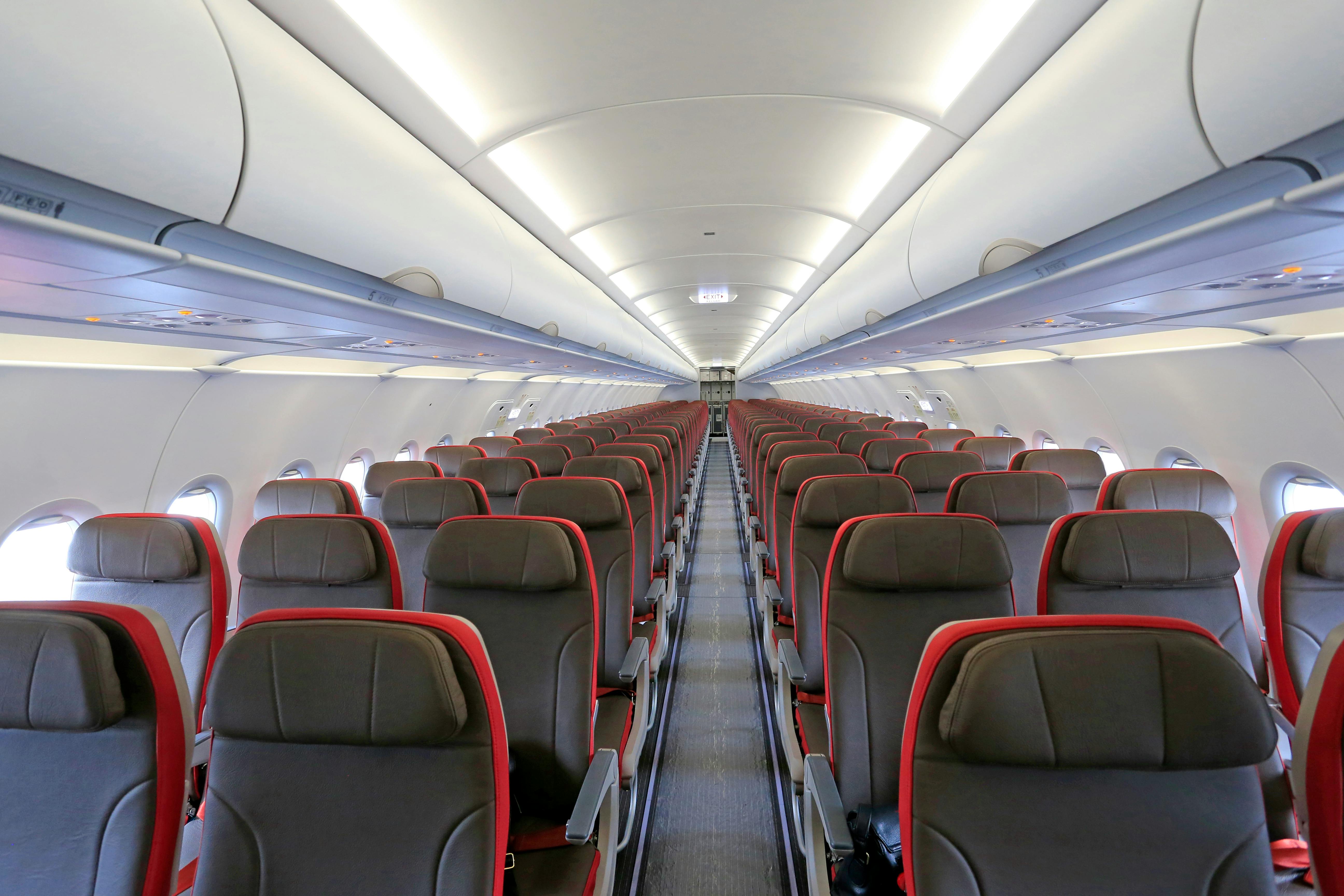
In a 150-seat passenger aircraft, a segment of the environmental control air duct elbow was previously a four-piece thermoplastic assembly glued and bracketed. After switching to industrial FDM one-piece Ultem 9085, the assembly became a single part, reducing weight, installation time, and part count; Ultem 9085 is already FAR 25.853 Appendix F compliant for such locations. The reason 3D printing triumphs here is not "speed," but that molding complex single-piece curved geometries is expensive, while printing them is almost free, and the material itself is FST compliant—additive manufacturing did not compromise the fire protection solution, but rather rewrote the economics while maintaining it.
Data Center Cabinet Cable Management Brackets

A hyperscale cloud provider standardized its cabinet design, but each co-location facility has different incoming cable entry points. Instead of stocking 20 types of injection-molded cable management bracket SKUs, operations directly print custom brackets using SLS FR PA12 on demand. Unit costs are higher than injection molding, but total costs are lower—no tooling, no dead inventory, and the brackets themselves pass UL 94 V-0, complying with data center fire safety regulations for non-metallic components inside cabinets. Flame retardancy acts as a filter for which materials are qualified to enter this scenario, and 3D printing makes inventory and lead times simultaneously achievable.
DFM: Designing to "Certification Standards," Not "Minimum Wall Thickness"
The most common failure mode for flame-retardant 3D printed parts is not printing defects, but geometrically feasible designs that do not meet certification. The solution is a disciplined set of defaults. Design critical burning wall thickness to be above the material's V-0 certified thickness plus a safety factor (if the material is V-0 at 1.5 mm, design critical walls to 1.8 mm or greater); orient the part so that support contact does not occur on any surface that will undergo burning tests, CTI tests, or long-term electrical contact; do not paint, apply conformal coatings, or solvent wipe tested surfaces, unless the coating is independently listed.
Two other habits yield particularly high returns. Incorporate Z-direction anisotropy into the design—tensile and impact strengths are typically 20–30% lower in the Z-direction; if flames could propagate along layer lines, ensure the primary flame propagation direction crosses layers rather than runs parallel to them. Also, directly draw witness coupons into the CAD: embed a tab of the same thickness as the certified feature next to the part or within the same build, so that the certification lab receives native specimens produced under the exact same process conditions as the shipped part.
Do / Don't Checklist
| Do | Don't |
|---|---|
| Read UL 94 rating and test thickness together | Assume V-0 automatically applies to thinner walls |
| Lock down standard (UL / IEC / FAR / EN) first, then select material | Only look for "flame retardant" and pick a material |
| Add IEC 60112 CTI spec for high-voltage electrical parts | Only specify UL 94 for high-voltage parts |
| Keep critical surfaces bare or use UL 746 listed coating | Claim V-0 after painting |
| Embed witness coupons in every build | Reuse supplier's coupons from months ago |
| Adjust orientation to avoid support contact on test surfaces | Let automatic orientation place critical surfaces on supports |
| Perform consistency checks between batches | Assume delivered material matches datasheet |
Practical Checklist
Keep only this one checklist, intentionally—use it at three critical times: design review, pre-print submission, and first article inspection.
- Applicable standards specified on drawing: UL 94 V-0 @ X mm, CTI ≥ Y V, FST / FAR 25.853 / EN 45545 as needed
- Every critical burning wall meets or exceeds certified thickness with safety factor
- Material grade and batch traceability requirements specified
- Surface finish noted if certified surfaces remain bare
- Orientation adjusted to avoid support contact on test surfaces
- Witness coupons embedded in the same build
- Printing parameters consistent with parameters used for material certification
- First article acceptance: Witness coupon burn test performed and recorded
- Dimensional measurement confirms critical burning wall thickness meets specifications
- If coated, coating is independently listed or re-tested
Common Mistakes and How to Avoid Them
| Mistake | Why it Fails | How to Avoid |
|---|---|---|
| Assuming V-0 automatically extends to thinner wall thicknesses | UL 94 ratings are tied to test thickness; no data for thinner sections | Design critical burning walls to be above test thickness and include safety factor |
| Painting the entire V-0 surface | Coatings alter burning behavior, invalidating original test configuration | Keep critical surfaces bare, or use UL 746 listed coating stacks |
| Missing CTI specifications for high-voltage parts | UL 94 does not test long-term electrical tracking under moisture; HV parts fail in humidity | Add IEC 60112 CTI requirements (most HV use ≥ 400 V; most severe scenarios use 600 V) |
| Support marks inside connector cavities | Rough surfaces collect dirt and moisture, creating CTI failure paths | Orient to avoid support contact on critical electrical surfaces |
| Treating "FR-like" resins as certified materials | Some resin formulations may delay flame but lack third-party certification | For certified parts, only select material grades with UL 94 and IEC certifications |
Key Design Takeaways
Treat flame retardancy as a stack of specifications (UL 94 + CTI + FST, as applicable), not a single property. Among the three routes—FDM PEI, SLS / MJF FR PA12, resin FR black resin—the logic for selection is environment → standard → material → process, not vice versa. Remember one thing when designing: UL 94 ratings are always accompanied by a test thickness; any area with wall thickness thinner than the certified thickness is not within the scope of certification. Incorporating this point into every flame-retardant part's DFM checklist will help you avoid most certification failures.


0 comments