
A Ti6Al4V aerospace bracket, weighing 182 grams when removed from the DMLS build plate, might look like a finished product, but it isn't. Roughly 600 MPa of residual stress is locked within its walls, the support lattice is still fused to the 15 mm build plate, and the surface roughness is Ra 9.2 micrometers. Only after stress relief at 650°C for four weeks, wire EDM removal, HIP at 100 MPa and 920°C, age hardening, 5-axis machining with a 0.6 mm datum allowance, and finally glass bead blasting, does it weigh 176 grams and truly become airworthy. Post-processing is not an add-on step; it accounts for 40% of the cost but determines 100% of the functionality.
Why Metal Additive Manufacturing Cannot Be Shipped Directly
Laser powder bed fusion builds melt pools with cooling rates of 10^5 to 10^6 K per second, leaving three realities: anisotropic grains, residual tensile stress approaching yield strength, and 0.1–0.3% subsurface porosity. Certified parts for aerospace, medical, and pressure vessel applications must address these three issues sequentially for any dimensional measurement to be meaningful.
The following processes must be performed in sequence; omitting any step will accumulate defects: a stressed part directly wire-cut might warp by 2 mm; heat treatment after machining can cause datum shifts; if a part has open-surface porosity, performing HIP prematurely will only smooth the surface. The sequence determines the outcome, and designers must confirm this sequence before submitting drawings.
Complete Post-Processing Chain
All production-grade metal additive manufacturing projects use a subset of these eight sequential stages. The table below outlines the standard sequence and purpose.
| # | Stage | Purpose | Common Equipment | Skippable Scenarios |
|---|---|---|---|---|
| 1 | Build Plate Stress Relief | Reduce residual stress before cutting | Vacuum/Inert Atmosphere Furnace | Small aluminum parts with very low stress |
| 2 | Part Removal | Separate part from build plate | Wire EDM, Bandsaw | — |
| 3 | Support Removal | Remove lattice and attachment points | Pliers, CNC, Grinding | Support-free design |
| 4 | Solution/Heat Treatment | Set microstructure and hardness | Vacuum Furnace | Printing already achieves final state |
| 5 | HIP (Hot Isostatic Pressing) | Close internal porosity | Hot Isostatic Press | Non-fatigue, non-pressure parts |
| 6 | Aging/Precipitation | Establish final strength | Atmosphere or Vacuum Furnace | Non-precipitation hardening alloys |
| 7 | CNC Machining | Critical feature tolerances | 3/5-axis Milling/Turning | All features have loose tolerances |
| 8 | Surface Treatment/Coating | Appearance, corrosion resistance, fatigue resistance | Sandblasting, Tumbling, Electropolishing, Anodizing | Only internal mating surfaces |
Stress Relief: The Uncompromising First Step
Parts still attached to the build plate should undergo stress relief in an inert or vacuum atmosphere before any cutting. This typically takes hours, with slow heating to avoid additional deformation.
| Alloy | Temperature | Soak Time | Atmosphere | Notes |
|---|---|---|---|---|
| Ti6Al4V | 640-670 °C | 3-4 hours | Argon or Vacuum | Below β transus temperature |
| Inconel 718 | 650-760 °C | 1-2 hours | Vacuum | Before solution treatment |
| Inconel 625 | 870 °C | 1 hour | Vacuum | Single stage sufficient for most applications |
| AlSi10Mg | 300 °C | 2 hours | Air (ambient) | Below T6 |
| 17-4 PH Stainless Steel | 650 °C | 2 hours | Vacuum/Argon | Before H900/H1025 aging |
| 316L Stainless Steel | 650-900 °C | 1-2 hours | Vacuum | Higher temp for full annealing |
| CoCr | 1150 °C | 1 hour | Vacuum | Often combined with HIP |
Heat Treatment Curves for Various Alloys
After support removal, dedicated heat treatment cycles determine the final mechanical properties. T6, solution aging, and precipitation hardening correspond to different alloy families.
| Alloy | Cycle | First Stage | Second Stage | Target Property |
|---|---|---|---|---|
| AlSi10Mg | T6 | Solution 520°C/1h Water Quench | Aging 160°C/6h | UTS approx. 330 MPa |
| Ti6Al4V | Annealing | 700-800°C/2h Furnace Cool | — | UTS approx. 950 MPa, Ductility |
| Ti6Al4V | STA | 955°C/1h Water Quench | Aging 540°C/4h | UTS approx. 1100 MPa |
| Inconel 718 | Solution + Double Aging | 980°C/1h | 720°C/8h + 620°C/8h | UTS approx. 1270 MPa |
| 17-4 PH | H900 | Solution 1040°C/30min | Aging 480°C/1h | UTS approx. 1310 MPa |
| CoCrMo | Solution Anneal | 1150-1220°C/4h | — | Biocompatible microstructure |
Hot Isostatic Pressing: Key for Fatigue Parts
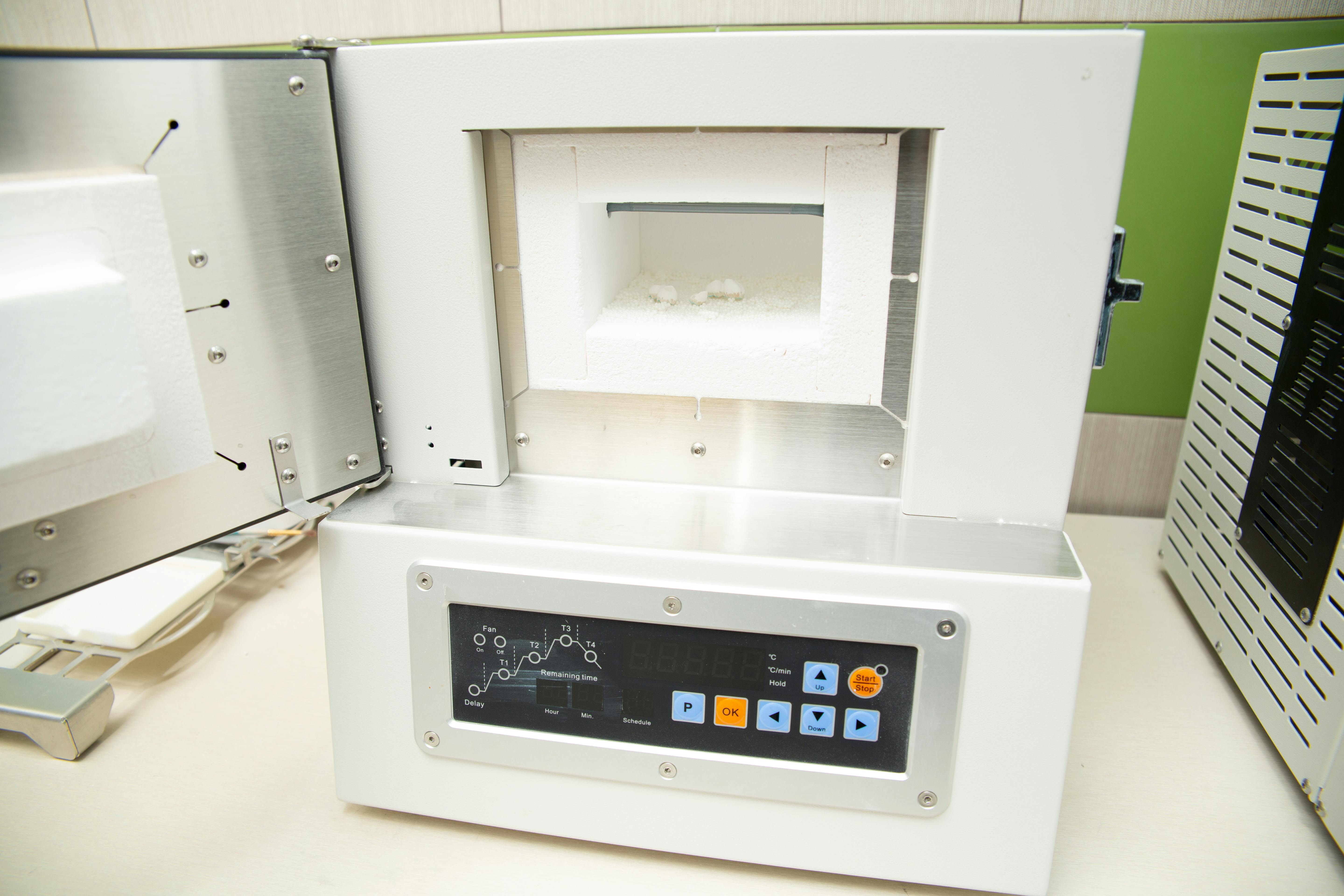
HIP applies isotropic gas pressure at high temperatures, combining pressure with plastic flow to close residual porosity that cannot be eliminated by printing. It is essential for rotating parts, critical flight components, or pressure-bearing parts, and strongly recommended for any part with fatigue life specifications.
| Alloy | Pressure | Temperature | Soak Time | Fatigue Life Improvement |
|---|---|---|---|---|
| Ti6Al4V | 100 MPa | 920°C | 2 hours | 3-10x |
| Inconel 718 | 100 MPa | 1160°C | 4 hours | 5-15x |
| Inconel 625 | 100 MPa | 1120°C | 4 hours | 5-10x |
| AlSi10Mg | 100 MPa | 500°C | 2 hours | 2-5x |
| 17-4 PH | 100 MPa | 1120°C | 4 hours | 3-8x |
| CoCrMo | 100 MPa | 1200°C | 4 hours | 5-10x |
CNC Machining: Allowance and Datum Strategy
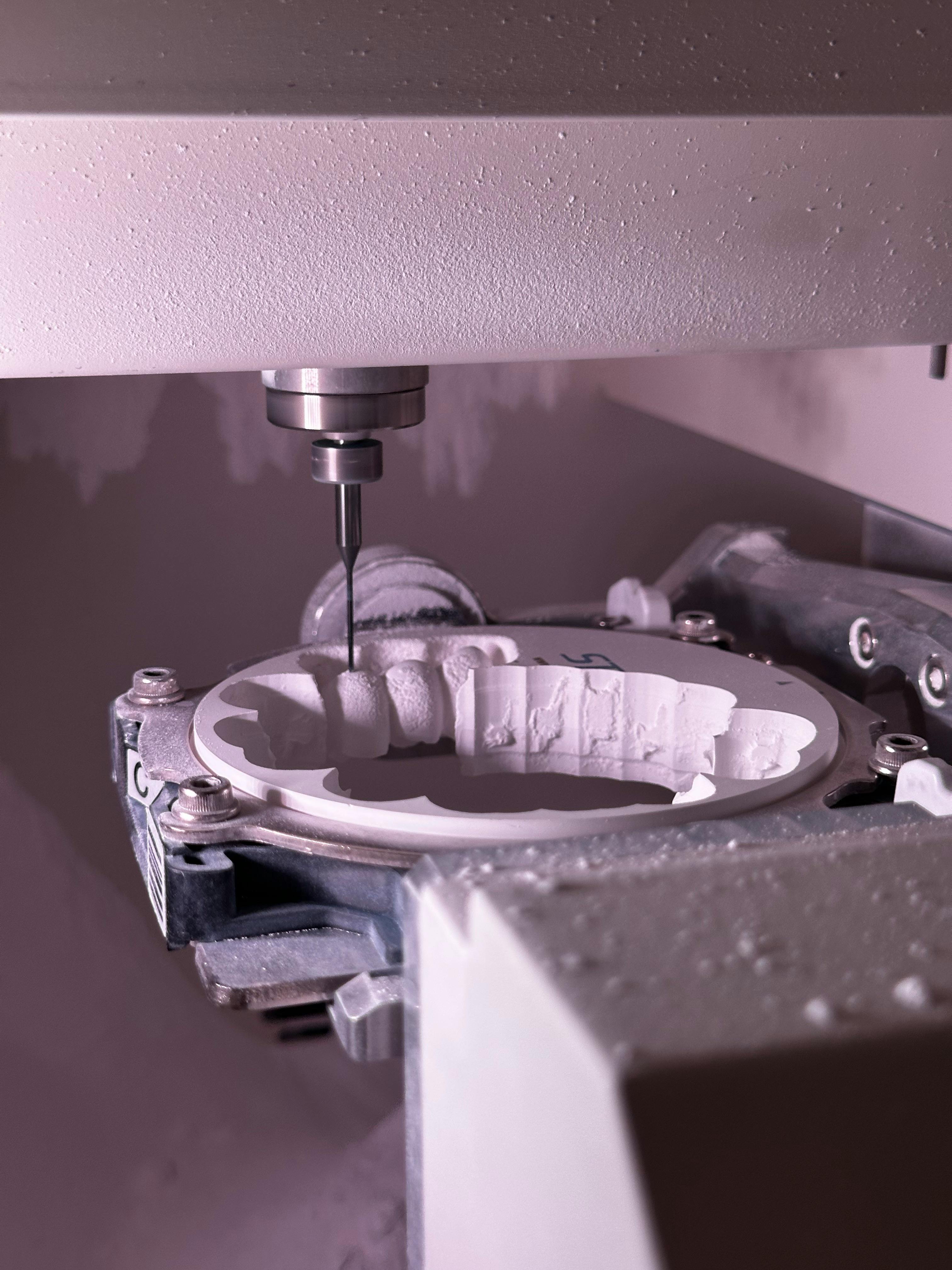
Print state XY tolerance is approximately ±0.2 mm, and Z tolerance is ±0.3 mm. For tighter tolerances, machining allowance must be left; add material only where needed, as excessive mass prolongs print time and increases HIP cost.
| Feature | Recommended Allowance | Reason |
|---|---|---|
| Flat Datum | 0.6-1.0 mm | Eliminate warp and roughness |
| Bearing Hole | Radial 0.4-0.8 mm | Concentricity <0.02 mm |
| Threaded Hole | Print undersize by 0.3-0.5 mm | Tap after heat treatment |
| Seal Groove | 0.3-0.5 mm | Ra <0.8 |
| Mating Flange | 0.5-0.8 mm | Flatness <0.05 mm |
| Non-critical Cosmetic Surface | 0 mm | Retain print state |
Application Cases: Three Production Post-Processing Stories
Ti6Al4V Satellite Bracket Grows 0.4 mm During Heat Treatment
A 140 mm topologically optimized antenna bracket was printed on four SLM systems by a European Tier-1 supplier. Initial prototypes fully conformed to CAD dimensions on the build plate, but failed inspection after STA heat cycling – four mounting holes shifted radially by 0.38 mm, exceeding the 0.1 mm tolerance.
The team rebuilt the post-processing workflow around predictive deformation. They used Simufact heat treatment simulation to generate a compensated scaling mesh of 0.994 in X and Y directions, moved heat treatment before machining, and revised all four mounting holes to be CNC-machined after HSK fixture alignment. Over eight consecutive batches, with four parts per batch, hole displacement was reduced to within 0.03 mm.
Key design actions: Incorporate heat treatment into dimensional chain simulation, pre-compensate for shrinkage direction; re-design all holes with tolerances less than 0.1 mm for post-heat treatment machining; allow 0.8 mm for datum surfaces; clearly mark drawings with "Dimensions measured after heat treatment and CNC completion."
Inconel 625 Exhaust Manifold Passes Fatigue Test with HIP
A racing exhaust manifold only achieved 60% of its specified life in vibration tests. CT scans revealed 0.12% residual porosity concentrated at the lattice-to-solid transition. After a single HIP cycle at 100 MPa, 1120°C for 4 hours, fatigue life improved by 7.8 times, with three consecutive batches passing all tests.
Anodized AlSi10Mg Drone Casing for Coastal Service
A coastal inspection drone casing showed visible corrosion after 40 flight hours. Bare AlSi10Mg salt spray tests failed within 96 hours. After T6 treatment, vapor honing to Ra 3.2 micrometers, and then Type II anodizing with sealing, zero corrosion was observed after 800 hours of salt spray, and surface resistance met ESD specifications.
Do's and Don'ts
| Do | Don't |
|---|---|
| Stress relieve on the build plate | Wire EDM parts without stress relief |
| Specify heat treatment cycles on drawings | Just write "per manufacturer standard heat treatment" |
| Add machining allowance only for toleranced features | Leave 1 mm allowance for the entire part |
| HIP fatigue and pressure parts | Assume printing eliminates porosity |
| Inspect datums after heat treatment | Only inspect after machining |
| Coat or passivate parts for corrosive environments | Directly deliver bare parts for outdoor use |
Common Errors
| Error | Consequence | Prevention |
|---|---|---|
| Part removal without stress relief | Deformation of 1-2 mm, scrap | Anneal on build plate first |
| Skipping HIP for fatigue parts | Premature crack initiation | Standard HIP for critical parts |
| Machining before heat treatment | Datum shift after thermal cycling | Heat treat first, then machine |
| No shrinkage compensation | Hole offset 0.2-0.5 mm | Use simulated scaling factors per alloy |
| Electropolishing deep channels | Uneven material removal | Use flow-through fixtures or avoid |
| Bare aluminum alloy for marine environments | Corrosion within 100 hours | Type II anodizing with sealing |
| HIP different alloys in the same furnace | Contamination, carburization | Dedicated HIP recipes |
Pre-Release Checklist
Before signing off on a metal additive manufacturing batch release, confirm each item. Any omission often results in non-conforming rework weeks later.
- Stress relief certification attached (alloy, temperature, soak time, atmosphere)
- Heat treatment and HIP curves reviewed, thermocouple and setpoint error <5°C
- CMM report uses post-machining datums, not pre-machining datums
- Ra roughness measured on at least three functional surfaces
- Corrosion protection applied per drawing (anodizing, passivation, coating)
- Powder batch traceable to finished part serial number
- Tensile and micro-examination of companion coupons passed
- Non-destructive inspection completed for critical parts (CT, penetrant, ultrasonic)
Design Considerations
Treat post-processing as part of the CAD model, not an extra service purchased from a vendor. At the concept stage, mark machining allowances, compensate for shrinkage, specify heat treatment recipes, and decide whether to HIP. Parts that ship on time and pass certification have always addressed these issues at the design stage.
A good rule of thumb: if you cannot describe every step that occurs between the end of printing and boxing the part, it is not ready for production. Clearly document every step, and the 40% post-processing cost will become predictable instead of explosively uncontrolled.


0 comments