
A North American athletic shoe brand needed 18,000 pairs of lattice midsoles per month for a Q3 launch. If they opened a TPU injection mold, each size would cost USD 220,000 and have a lead time of 14 weeks, but the team only had 6 weeks. They turned the project to Carbon DLS, using EPU 41, printing 48 pairs at a time on an M2 platform with a 9-hour cycle time, followed by 4 hours of post-curing at 120°C. Before the 14-week mold deadline, they had shipped over 40,000 pairs and dynamically adjusted the lattice geometry three times—each time only requiring modifications to the parametric model, without any molding costs.
This outcome is precisely why Carbon's Digital Light Synthesis is positioned as a mass production process, rather than a prototyping tool. However, it can only deliver that "mass production" reliability when design, resin families, and post-processing chains are all in place.
This guide will sequentially explain DLS forming mechanisms, six truly important mass production resins, DFM figures actually controlled by Carbon partners, the two-stage curing process, and three case studies from prototyping to mass production. The goal is to provide design teams with sufficient data to determine whether DLS should be added to their process list.
What exactly is Carbon DLS?
DLS projects UV images through an oxygen-permeable window at the bottom of the resin tank. Oxygen creates a "dead zone" approximately 20 to 30 microns thick, preventing the resin from sticking to the window surface, allowing the print platform to continuously lift upwards instead of peeling off each layer. This makes Z-axis speeds 3 to 5 times faster than traditional DLP, while reducing Z-axis weaknesses caused by layer peeling.
Equally critical, green parts are not final parts. Carbon's production resins are all dual-cure systems: the UV network solidifies during printing, and then a second chemical reaction—usually polyurethane—is triggered by a heat cycle to truly establish mechanical properties. Therefore, all design decisions must be based on the post-cured state, not the green parts fresh off the machine.
| Item | SLA / DLP | Carbon DLS |
|---|---|---|
| Forming Action | Layer-by-layer peeling | Continuous pulling |
| Window Interface | Peelable film | Oxygen-permeable dead zone |
| Curing Stage | Single UV cure | UV cure + thermal post-cure |
| Typical Z-axis Speed | 10–30 mm/hour | 60–120 mm/hour |
| Production Resins | Limited | EPU, RPU, EPX, MPU, FPU, CE |
| Target Volume | 1–500 units | 200–50,000 units |
Resin families that truly impact mass production
Carbon's resin list is long, but projects that truly enter mass production usually converge on the same six. EPU 40 and 41 are the main elastomers behind lattice midsoles and gaskets; RPU 70 is the most common rigid housing resin; EPX 82 is the first choice for higher HDT or impact toughness; MPU 100 and FPU 50 are for medical biocompatibility and semi-rigid hinge scenarios, respectively; CE 221 is currently the highest HDT resin in the Carbon ecosystem, suitable for under-the-hood parts.
First, choose the resin, then let it constrain the geometry. The Shore hardness, elongation at break, and HDT of this family can differ by more than an order of magnitude, so DFM rules that are safe for RPU 70 may not apply to EPU 41; wall thicknesses that are fine for EPU 41 may fail when subjected to the thermal loads encountered in a CE 221 design.
| Resin | Category | Hardness / Tensile Strength | Elongation at Break | HDT @ 0.45 MPa | Typical Uses |
|---|---|---|---|---|---|
| EPU 40 | Elastomer | 68A Shore | 300% | — | Conformable lattices, seals |
| EPU 41 | Elastomer | 68A Shore | 280% | — | Lattice midsoles, helmet liners |
| RPU 70 | Rigid Engineering | 40 MPa | 100% | 90°C | Consumer electronics housings, brackets |
| EPX 82 | Tough Engineering | 82 MPa | 9% | 130°C | Connectors, conduits, housings |
| MPU 100 | Medical Rigid | 45 MPa | 12% | 88°C | Biocompatible devices |
| FPU 50 | Semi-rigid | 27 MPa | 220% | 80°C | Living hinges, snap-fits |
| CE 221 | High Temperature | 90 MPa | 3% | 231°C | Under-the-hood, electrical coil forms |
DFM numbers truly controlled by Carbon partners
The resolution of projection-based photopolymerization can easily tempt designers to specify features that can be printed but fail during post-curing or handling. The following table shows the numbers that contract manufacturers will accept without much discussion; any dimensions below these should be reviewed on a case-by-case basis.
| Feature | Rigid Resins | Elastomers | Notes |
|---|---|---|---|
| Minimum Wall Thickness | 1.0 mm | 1.5 mm | Below this value, warpage during post-curing will significantly increase |
| Minimum Lattice Strut | 0.8 mm | 0.6 mm | Elastomers can tolerate thinner struts |
| Raised Features | 0.4 mm deep, 1.5 mm high | Not Recommended | For EPU, use recessed features |
| Fit Clearance | 0.3 mm | 0.5 mm | Increase clearance when rigid and elastic parts fit together |
| Unsupported Overhang | 1.0 mm | 0.5 mm | Supports are needed beyond this value |
| Self-supporting Angle | 45° from horizontal | 35° from horizontal | Depends on cross-section |
| Minimum Hole Diameter | 0.8 mm | 1.2 mm | Critical holes recommended to be drilled post-processing |
Two-stage curing that defines the part
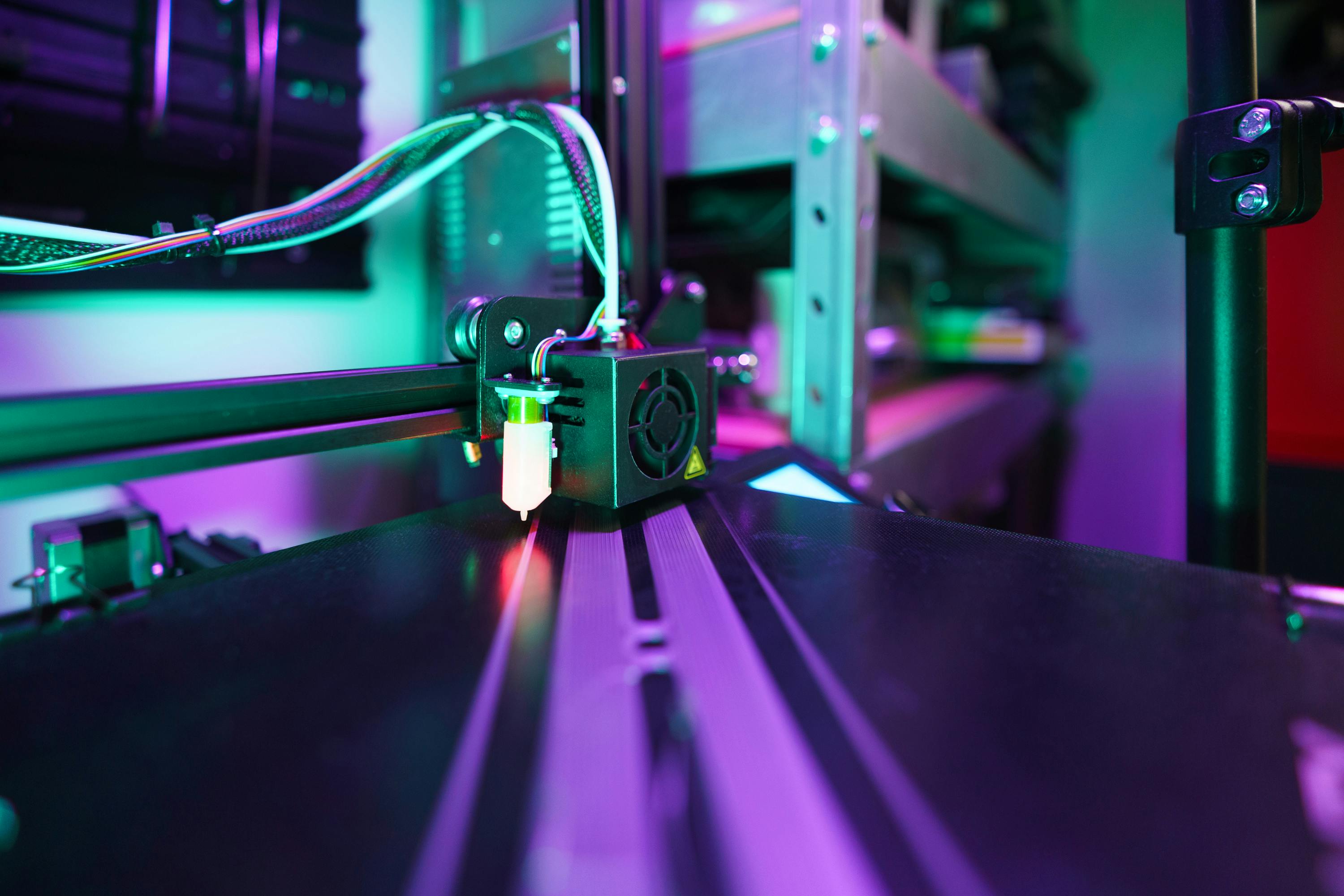
When green parts are removed from the printer, they are in a solvent-swollen state with an incompletely formed network. The standard post-processing procedure is to clean off unreacted resin in Carbon's Smart Part Washer (usually IPA first, then clean solvent, both for 5 minutes), allow them to fully dry, and then place them in a thermal curing oven. Residual solvent during thermal curing is the primary cause of surface blistering and part failure.
The oven cycle itself is resin-specific. EPU 41 requires 120°C for 4 hours; RPU 70 also requires 120°C for 4 hours, but with a different temperature ramp; EPX 82 requires 130°C for 2 hours, and CE 221 requires staged temperature increases to 190°C. Using the wrong cycle will either result in incomplete post-curing (compromising mechanical properties) or deformation of the part in the oven.
| Resin | Washing | Thermal Curing | Temperature Ramp | Target Change |
|---|---|---|---|---|
| EPU 41 | Two stages of IPA, 5 mins each | 120°C / 4 hours | Staged | Establish elastomer network |
| RPU 70 | Two stages of IPA, 5 mins each | 120°C / 4 hours | Linear | Stiffness and HDT |
| EPX 82 | Two stages of IPA, 5 mins each | 130°C / 2 hours | Linear | Toughness and HDT |
| MPU 100 | Validated IPA | 120°C / 4 hours | Linear | Biocompatible network |
| FPU 50 | Two stages of IPA, 5 mins each | 110°C / 8 hours | Gradual | Polypropylene-like behavior |
| CE 221 | Two stages of IPA, 5 mins each | 190°C / 2 hours + ramp | Stepped | Cyanate ester network |
Production volume range where DLS outperforms injection molding
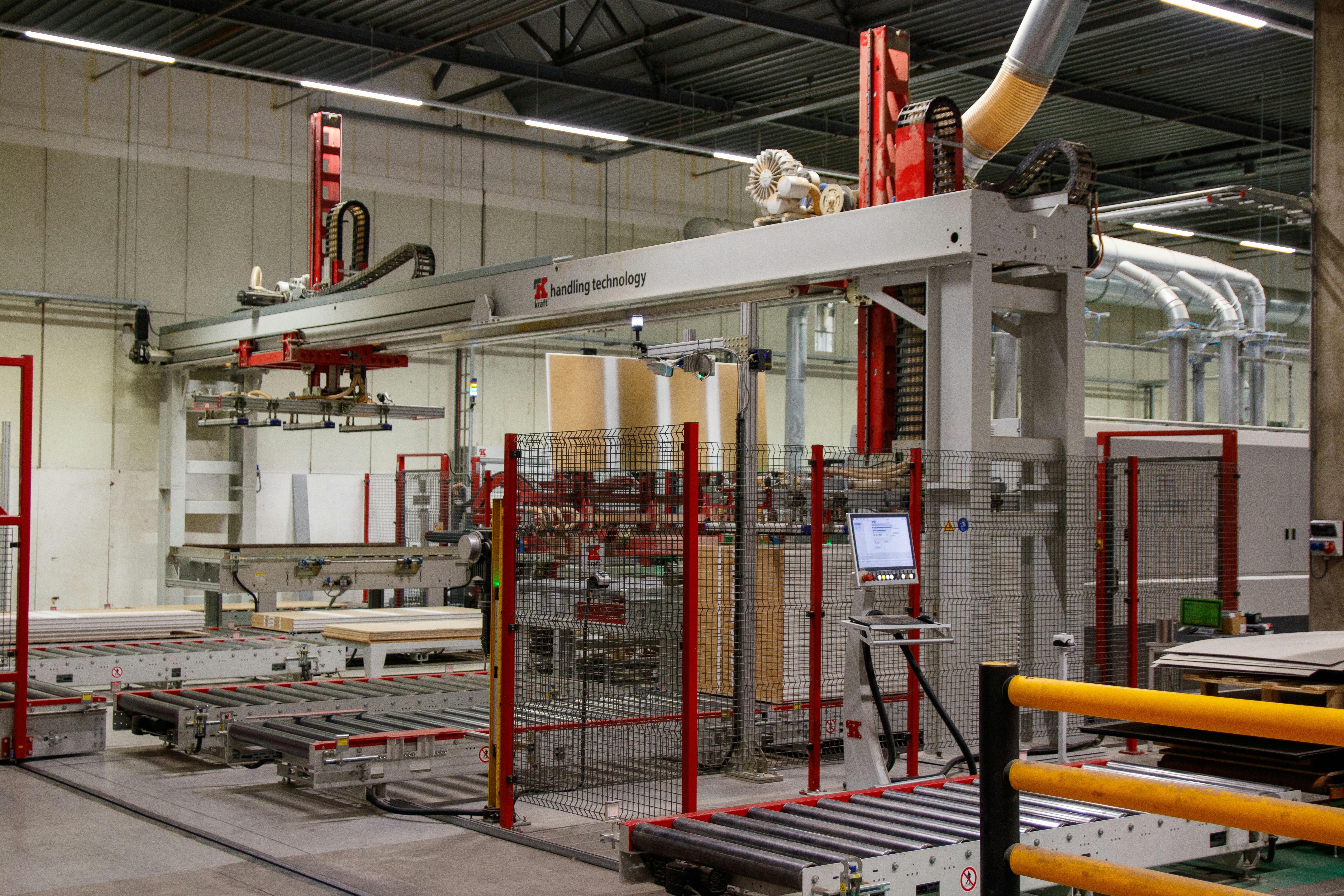
The old rule that "over 1,000 units should be injection molded" is too crude for parts containing elastomers, lattices, or those that undergo frequent revisions. When amortization of molds, revision costs, and the option to change geometry mid-production are all factored in, DLS remains competitive in scenarios significantly exceeding 1,000 units. The largest disparity occurs when revision frequency is high, customization needs are clear, or when the geometry simply cannot be made with molds.
Applications in actual mass production projects
Adidas 4D Lattice Midsoles
Key design action: Adidas collaborated with Carbon to advance 4D midsoles from athlete prototypes to retail mass production scale, replacing TPU foam with EPU 41 lattice and adjusting it section by section on the footbed. Each midsole has approximately 12,000 struts, with diameters varying between 0.6 and 1.4 mm; the struts are thicker in the heel impact zone and thinner in the forefoot flex zone. One M2 platform prints 48 pairs of size 9 midsoles in about 9 hours, with thermal curing at 120°C for 4 hours.
This case is crucial because it is no longer just a demonstration. Since 2017, Adidas has shipped millions of pairs of DLS-printed midsoles, forcing Carbon's internal quality systems—print monitoring, resin batch traceability, oven validation—to achieve true mass production discipline. Design teams looking to benchmark this project should assume that every lattice unit is parametrically defined, and every size is regenerated from the same geometric definition, rather than manually modified.
The implication for other industries is that lattices are not a gimmick, but a key mechanism that allows a single resin to simultaneously achieve soft compression in the heel, stiffer rebound in the forefoot, and stable midsole geometry, without multi-material injection molding or bonded foam. The design problem shifts from material selection to lattice topology.
Riddell SpeedFlex Diamond Helmet Liners
Riddell's American football helmet liners use Carbon EPU lattice, adjusted based on player head scans and impact history. Each helmet has approximately 140,000 lattice units, each regenerated for the specific player, printed on an M2 platform, and then post-cured at 120°C for 4 hours. The seasonal production volume is not large—only a few thousand units—but this is the clearest example of large-scale customization that molds simply cannot achieve. The design implication is: DLS most rewards geometries where "every piece is different," because as long as the parametric model is stable, the marginal cost of changing geometry per piece is zero.
Bridge Production of Ford Turbocharger Ducts
Ford used Carbon EPX 82 for bridge production of turbocharger intake ducts for a limited-edition performance car model before the official mold was completed. The volume was approximately 500 units per month, lasting for 9 months; the parts operate at temperatures close to 120°C under the hood, and the EPX 82's 130°C HDT provides a safety factor of about 1.1. The overall cost was lower than the quotation for injection molding the same part, and shipments were on time during the parallel mold development. The implication of this case is: DLS's strongest role is often not as a permanent process, but as a bridge that keeps the entire launch schedule on track.
Carbon DLS Do's / Don'ts
| Do | Don't |
|---|---|
| Select resin before locking geometry | Design with general rigid plastics first, then select resin later |
| Determine dimensions based on post-cured state | Approve drawings based on green part measurements |
| Break down thick cross-sections with lattices | Retain solid blocks exceeding 8 mm |
| Parametrize each lattice unit | Manually modify each strut |
| Validate oven cycle with standard test specimens | Only trust oven settings, no data recording |
| Include washing and drying time in the quotation | Ignore 30–45 minutes of pre-curing treatment |
| Use DLS as a bridge solution for 200–50,000 units | Force production above 100,000 units without re-evaluating costs |
Common mistakes and how to avoid them
| Mistake | Cause of Failure | How to Avoid |
|---|---|---|
| Applying RPU DFM to EPU 41 | Elastomer struts below 0.6 mm can tear during demolding | Apply resin-specific DFM at the first CAD review |
| Thick solid cross-sections | Residual solvent blisters during thermal curing | All cross-sections over 6 mm should be hollowed or latticed |
| Skipping secondary drying | Residual IPA will boil out in the oven | Allow to sit for 30–45 minutes after washing before curing |
| Directly using SLA supports for DLS | Continuous pulling requires different support densities | Regenerate supports in Carbon Print Prep |
| Insufficient HDT margin | Parts creep when service temperature is close to HDT | Use 0.8 × HDT as the design limit, or switch to EPX 82 / CE 221 |
| Treating green part tolerances as final | Shrinkage and relaxation during post-curing change fits | Base dimensions on post-cured test specimens, not green parts |
Pre-production checklist
Before putting Carbon DLS parts into mass production, please go through the following checklist with your contract manufacturer and quality responsible. There aren't many items, but they can catch most problems that only emerge in the first 100 units.
- Resin has been selected, and corresponding DFM rules applied
- All cross-sections exceeding 6 mm have been hollowed out or filled with lattice
- Lattice struts are parametrized and meet the minimum values for the chosen resin
- Washing and drying times have been allocated before thermal curing
- Oven recipe corresponds to the resin (temperature, time, ramp)
- Witness specimens are included in each print platform
- Drawing dimensions are based on the post-cured state, not green parts
- Production volume falls within the reasonable DLS range of 200–50,000 units
Key design takeaways
Carbon DLS is truly worth adding to the mass production process list when three conditions are met simultaneously: the part requires elastomers, lattices, or frequent revision flexibility; the volume is between a few hundred and tens of thousands of units; and the team is willing to treat two-stage curing as a true manufacturing step, not just a post-finishing touch. First, choose the resin, design according to its DFM figures, validate with post-cured test specimens, and compare costs with honest mold amortization. Once these habits are established, DLS will no longer be a novelty, but a bridge that quietly safeguards the product's launch schedule.


0 comments