
A 1.5 mm 304 stainless steel bracket showed cracks on the outer fiber after being formed with a 1.0 mm inside bend radius on a press brake. Nine out of the first forty pieces fractured. The correction method was straightforward: increasing the radius to 2.4 mm (1.6 t), rotating the bending axis 90 degrees relative to the rolling direction, and using a 12 mm V-die resulted in clean bends without fine cracks.
The sheet metal bend radius, K-factor, and feature placement determine whether the flat pattern can be reverse-calculated to the correct dimensions and whether the formed part can be bent without cracking. This guide compiles practical data for carbon steel, stainless steel, and aluminum alloys with thicknesses of 0.5–2.0 mm, as well as critical manufacturability judgments from actual cases.
How to Read These Rules
The following data assumes cold-rolled sheet metal, room temperature, and air bending with an 88-degree standard V-die. Coining/bottoming can reduce springback but requires 5–10 times the tonnage of air bending. The inside bend radius (IR) is measured from the inside surface, and the neutral layer is located K×t from the inside surface.
Treat thickness (t) as the primary variable: minimum IR, hole-to-bend distance, bend-to-edge distance, and slot distances are all scaled by t. If unsure, try with the geometrically largest allowed IR, then progressively tighten after a successful trial.
Minimum Inside Bend Radius by Material and Thickness
The table below covers the four most frequently quoted alloys in our factory. Values are for minimum IR when bending transverse to the rolling direction; if the bending axis is parallel to the rolling direction, multiply by 1.5.
| Material | 0.5 mm | 1.0 mm | 1.5 mm | 2.0 mm |
|---|---|---|---|---|
| Carbon Steel 1010 (CRS) | 0.5 mm (1.0 t) | 1.0 mm (1.0 t) | 1.5 mm (1.0 t) | 2.0 mm (1.0 t) |
| 304 Stainless Steel | 0.8 mm (1.6 t) | 1.6 mm (1.6 t) | 2.4 mm (1.6 t) | 3.2 mm (1.6 t) |
| 5052-H32 Aluminum Alloy | 0.5 mm (1.0 t) | 1.0 mm (1.0 t) | 1.5 mm (1.0 t) | 2.0 mm (1.0 t) |
| 6061-T6 Aluminum Alloy | 1.5 mm (3.0 t) | 3.0 mm (3.0 t) | 4.5 mm (3.0 t) | 6.0 mm (3.0 t) |
6061-T6 is an exception: high strength but low ductility, 3t is the practical minimum. For tighter radii, consider forming in 6061-O annealed condition and then heat-treating to T6, or switch to 5052-H32.
K-Factor and Bend Allowance
Bend allowance (BA) is the developed length of the bend section in the flat pattern, calculated by BA = (π/180) × angle × (IR + K × t). The K-factor varies with the IR/t ratio, as tight bends push the neutral layer inward, while wide bends return it to the geometric center.
| IR/t Ratio | K for Steel/Stainless Steel | K for Aluminum Alloy | Notes |
|---|---|---|---|
| 0.5 | 0.33 | 0.36 | Risk of cracking; verify with test pieces |
| 1.0 | 0.38 | 0.41 | Default for thin sheets |
| 2.0 | 0.42 | 0.44 | Stable, low springback |
| 3.0+ | 0.45 | 0.46 | Approaches neutral axis |
Example: 1.5 mm 5052 aluminum, 90 degrees, IR = 1.5 mm (IR/t = 1.0, K = 0.41). BA = (π/180) × 90 × (1.5 + 0.41 × 1.5) = 3.00 mm. The CAD flat pattern should be shortened by 1.50 mm on each side of the bend line.
Hole, Slot, and Edge Distances
Forming will stretch the material within approximately 4t of the bend line. Holes may become oval, tabs may tear, and PEM fasteners may shift position.
| Feature | Min. Distance to Bend Line | Min. Distance to Edge | Notes |
|---|---|---|---|
| Round Hole | 2.5 t + IR | 2.0 t | Measured edge-to-edge |
| Long Slot (Parallel) | 4.0 t + IR | 2.5 t | Long axis along bend line |
| Long Slot (Perpendicular) | 3.0 t + IR | 2.5 t | Less transverse deformation |
| PEM Stud/Nut | 3.0 t + IR | 2.0 D | D is PEM diameter |
| Extruded Countersink | 4.0 t + IR | 3.0 t | Add relief slots if violated |
If geometry inevitably violates these rules, add relief slots (1.5 t wide × 1.5 t deep) to prevent tearing. Holes near bends can be enlarged first, then re-punched after forming, or use PEM fasteners installed after forming and tapping.
Springback Compensation by Material
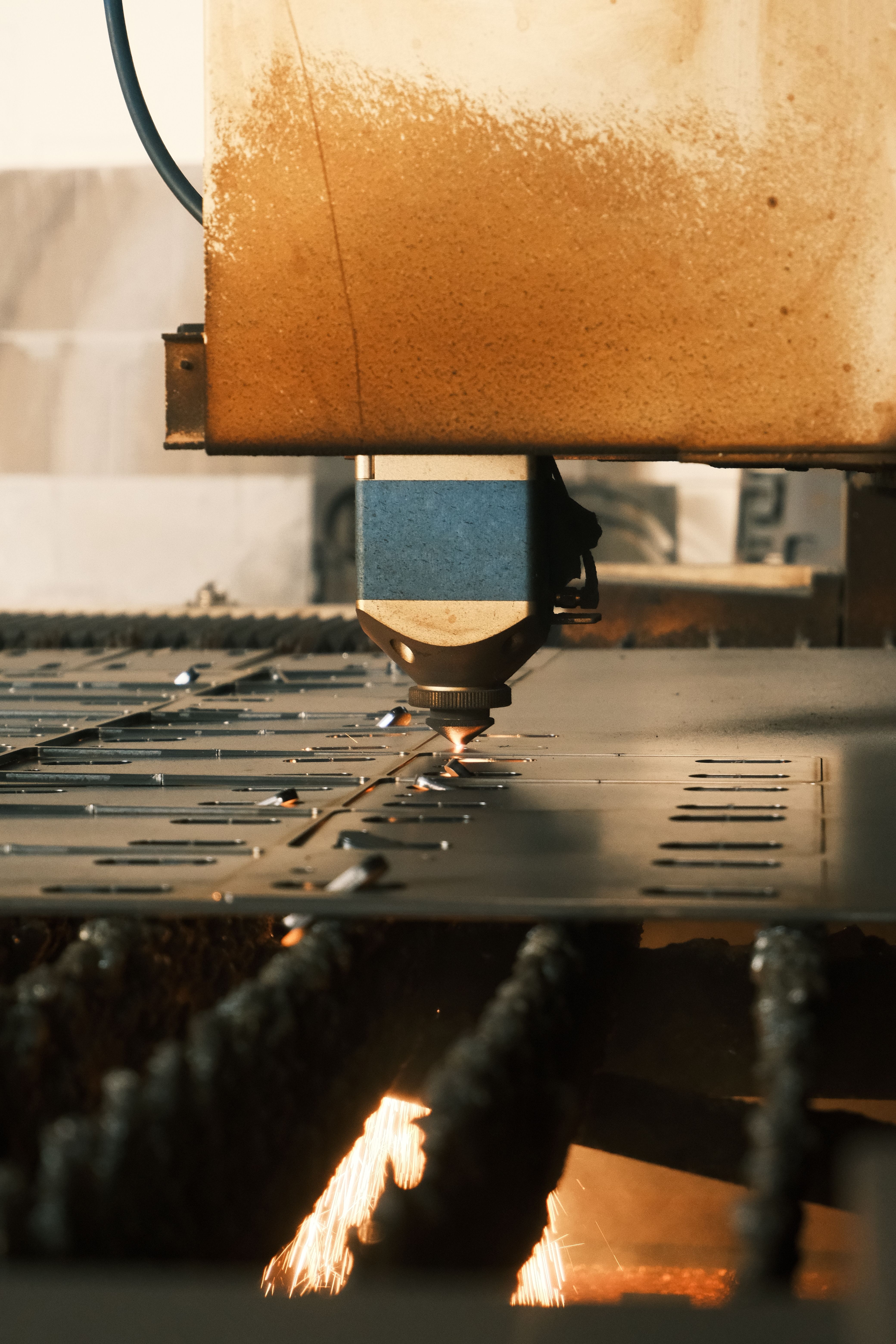
Springback results from elastic recovery after the punch retracts. Higher yield strength and larger IR/t result in greater springback, requiring compensation with an over-bend angle.
| Material | Springback at IR/t = 1, 90° | Required Over-bend Angle | Strategy |
|---|---|---|---|
| Carbon Steel 1010 | 1–2 degrees | 91–92 degrees | Air bending |
| 304 Stainless Steel | 3–5 degrees | 93–95 degrees | Reduce ram speed, bottoming |
| 5052 Aluminum | 2–3 degrees | 92–93 degrees | Air bending |
| 6061-T6 | 4–6 degrees | 94–96 degrees | Coining if angle is critical |
V-Die Selection and Die Marks
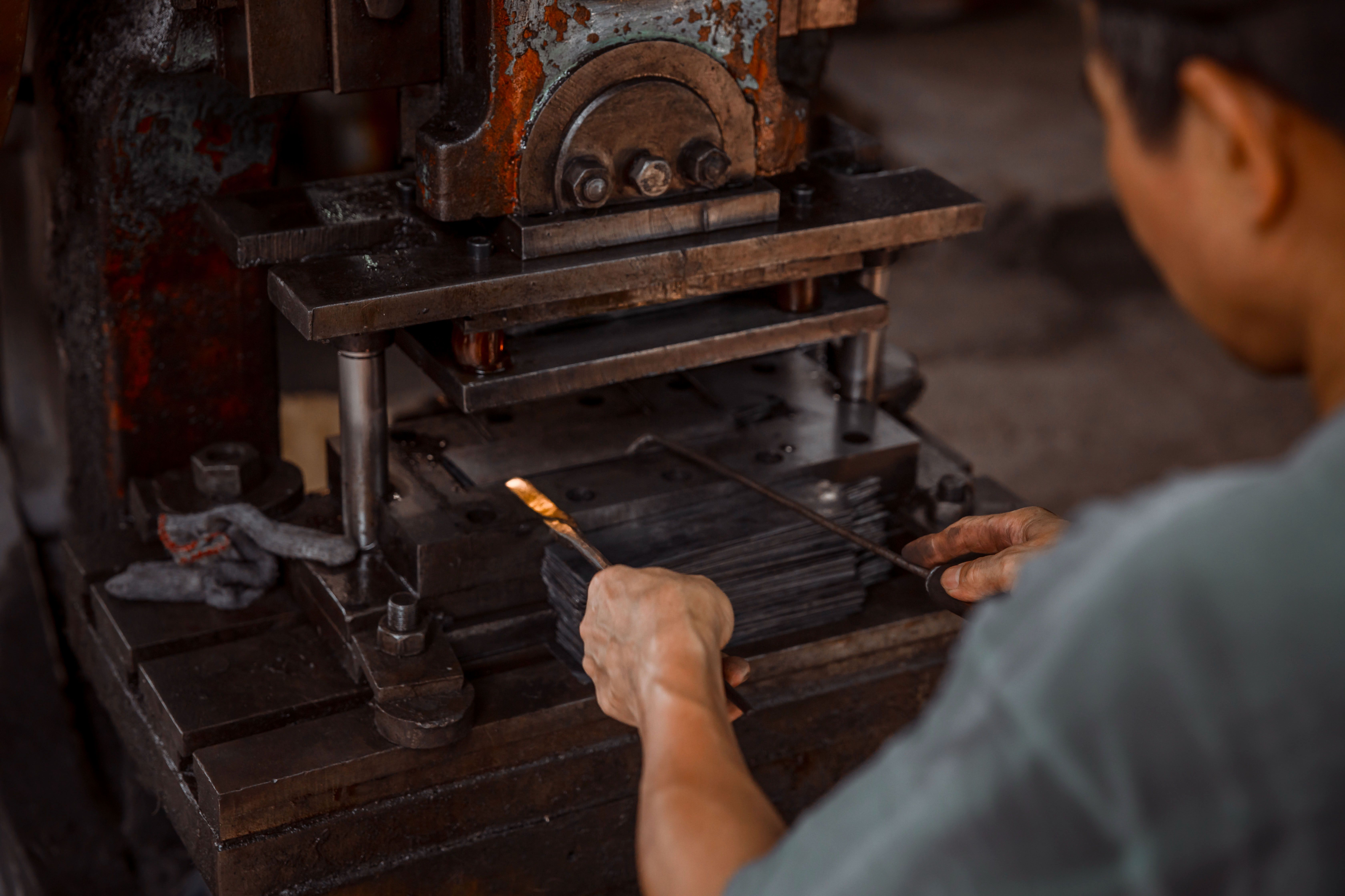
V-die opening width determines achievable IR: for thin sheets (<3 mm), use V = 6t; for medium sheets, V = 8t; for thick sheets, V = 10t. A narrower V results in a tighter IR but higher tonnage and may cause V-marks on the underside.
| Thickness | Recommended V-die | Resulting IR | Tonnage per meter (mild steel) |
|---|---|---|---|
| 0.5 mm | 4 mm | 0.7 mm | 1.0 ton/meter |
| 1.0 mm | 6 mm | 1.0 mm | 2.5 tons/meter |
| 1.5 mm | 10 mm | 1.7 mm | 3.4 tons/meter |
| 2.0 mm | 12 mm | 2.0 mm | 5.0 tons/meter |
Die marks on cosmetic surfaces can be reduced by using polyurethane V-pads, polished dies, or applying protective film before bending. For brushed stainless steel, position the polyurethane side towards the visible surface.
Application Cases
Electronic Enclosure Top Cover, 1.0 mm 5052
Four 90-degree bends, PEM studs 6 mm from the bend line. IR = 1.0 mm, BA = 1.83 mm per bend, K = 0.41. PEM studs were pressed after bending to ensure perpendicularity within 0.1 mm, and relief slots were added to the cover's wings to prevent corner tearing.
Server Rack Upright, 2.0 mm 1010 Steel
Hat-shaped cross-section with two 90-degree bends, IR = 2.0 mm, 12 mm V-die, 5 tons/meter. The long axis of the square slots is perpendicular to the bend line with a 7 mm clearance, preventing tearing under rated load.
Automotive Bracket, 1.5 mm 6061
Customer required 6061-T6 for rigidity. Bent in O-temper with IR = 4.5 mm (3t), then heat-treated to T6, and finally precision-milled the mounting holes; over-bent by 4 degrees, resulting in a final wing angle of 90 ± 0.5 degrees.
Recommendations and Avoidances
| Recommend | Avoid |
|---|---|
| Start with IR = t | Specifying zero radius or sharp corners on production drawings |
| Add 1.5 t × 1.5 t relief slots at wing ends | Hole-to-bend distance < 2.5 t without relief slots |
| Bend stainless steel transverse to the rolling direction | 6061-T6 with inside bend radius < 3 t |
| Control by wing length tolerance instead of bend angle tolerance | Accumulated bend angle tolerances tighter than ±0.5 degrees |
Common Mistakes
| Mistake | Failure Mode | Correction |
|---|---|---|
| IR copied from supplier catalog without re-validating K | Flat pattern off by 0.3–1.0 mm per bend | Conduct trials to measure and calibrate K |
| PEM part too close to bend | Stud tilt, damaged threads | Move 3 t + IR or install PEM after bending |
| Using the same V-die for different thicknesses | Inconsistent IR, springback drift | Change die based on V = 6–10 t |
| Stepped wings without relief slots | Wing base tearing | Add 1.5 t notch at wing end |
| 304 bent parallel to rolling direction | Outer fiber cracks | Rotate 90 degrees or enlarge to 2 t |
Pre-production Checklist
- Confirm material, temper, thickness, and rolling direction on the purchase order.
- Verify the minimum inside bend radius for all bends against the table above.
- Reverse-calculate at least one bend using BA = (π/180) × angle × (IR + K × t) and compare with the CAD flat pattern.
- Check hole, slot, and PEM part distances using the 2.5–4 t + IR rule.
- Note the V-die width (V = 6–10 t) on the process sheet.
- Add 1.5 t × 1.5 t relief slots where wing ends fall in the middle of the sheet.
- Specify the over-bend angle for springback on 304 stainless steel and 6061-T6.
- Plan the bending sequence to avoid interference between the last two bends and the tooling.
Design Considerations
Treat the bend radius, K-factor, and feature placement as a coupled system anchored by thickness. First, define IR, then calculate BA using the corresponding K-factor, and finally check hole and edge distances; release the flat pattern only after all three are validated.
Document the rolling direction, V-die width, and over-bend angle on the drawing; do not leave it to the operator's experience. Brackets with documented parameters can be reproduced consistently across different factories, unlike those relying solely on experience.
If unsure, try with the geometrically largest allowed IR; progressively tighten after successful trials. Tight bending is a process choice, not a default.


0 comments