
A Multi Jet Fusion PA12 tensile bar, fresh from the powder bed, has a density of approximately 1.01 g/cm³, a residual porosity of about 6.8%, an unblasted surface Ra of about 11 µm, and a tensile strength of 48 MPa, with nearly isotropic strength in the XY and Z directions. This is why MJF is often the default choice for physical parts that must snap, fasten, or withstand 200 hours of vibration in a drone body.
Designers who treat MJF as "just another SLS" will lose performance in three areas: making wall thicknesses too thick, misjudging clearances for moving parts, and specifying surface finishes that don't exist in the MJF post-processing chain. This article will sequentially explain the physical mechanism of MJF's fusing agent, currently mass-producible materials, key DFM values, and three functional part case studies to ensure your next production run of 50–2,000 pieces is successful.
MJF Fusing Agent Mechanism vs. Laser Sintering SLS
MJF jets a high-carbon black fusing agent where solidification is needed, then uses an infrared lamp to scan the entire layer at once. The agent absorbs infrared light, melting the surrounding PA12 in milliseconds; the detailing agent at the edges prevents melt diffusion. This is why MJF offers a higher level of dimensional accuracy than SLS and is four times faster.
| Item | HP MJF PA12 | Typical SLS PA12 | Why it matters |
|---|---|---|---|
| Part Density | 1.01 g/cm³ | 0.90–0.95 g/cm³ | Higher strength, fewer leak paths |
| Residual Porosity | Approx. 6.8% | Approx. 7.9% | Fewer micropores, better fatigue performance |
| XY / Z Tensile Strength | 48 / 48 MPa | 48 / 42 MPa | Nearly isotropic, almost direction-independent |
| Unblasted Ra | Approx. 11 µm | Approx. 15 µm | Smoother surface when fresh from powder |
| Original Color | Natural gray | Off-white | Better at hiding cosmetic marks |
| Time per Layer | Approx. 10 seconds | Approx. 40 seconds | Higher throughput per build |
MJF Materials Available for Purchase in 2026
The process is only half the decision – material is the half that truly locks in your environmental, electrical, and fire performance. The following materials are all certified on HP Jet Fusion 5200 series equipment and are already mass-producible and shippable by service providers.
| Material | Hardness / Modulus | Best Use | Notes |
|---|---|---|---|
| PA12 | D80 / 1,700 MPa | General functional parts, housings, fixtures | Moisture absorption approx. 1.3% |
| PA11 | D75 / 1,500 MPa | Impact parts and living hinges | Higher cost, longer lead time |
| PA12 Glass Beads | D82 / 2,500 MPa | Rigid supports, fixtures | Lower elongation at break (approx. 6%) |
| TPU Ultrasint 88A | 88A / 26 MPa Tensile | Seals, gaskets, sports grips | Only bead blasting, no tumbling |
| PA12 FR (V-0) | D78 / 1,800 MPa | Rails, cabins, electrical enclosures | Grey only, +30% cost |
| PP (BASF/HP) | D70 / 1,400 MPa | Chemical tanks, living hinges | Fewer service providers |
DFM Values Determining Yield
MJF is more tolerant of geometry than SLA or FDM, but there's still a relatively narrow optimal range, especially for features that must pass through powder removal, blasting, and handling. The table below is based on calibrated 520 machines and over 2 million manufacturing data points.
| Feature | Minimum Value | Recommended Value | Notes |
|---|---|---|---|
| Wall Thickness | 0.5 mm | 1.0 mm | Below 1.0 mm, batches will warp |
| Embossed Text | Line width 0.8, height 0.5 mm | 1.0 / 0.8 mm | Debossed text is more stable for recognition |
| Through Hole | 0.5 mm | 1.5 mm | For press fit, add +0.2 mm |
| Blind Hole Depth | 3× diameter | 5× diameter | Needs powder removal path |
| Clearance for Moving Parts | 0.3 mm | 0.4 mm | Sufficient for on-site printed hinges |
| Powder Removal Hole | 2 mm | 4 mm | At least one per ≥ 1 cm³ enclosed cavity |
| Snap-fit Cantilever | t=1.0, L=8 mm | t=1.2, L=10 mm | For >1,000 cycles, PA11 is recommended |
Post-Processing: What This Grey Skin Can Become
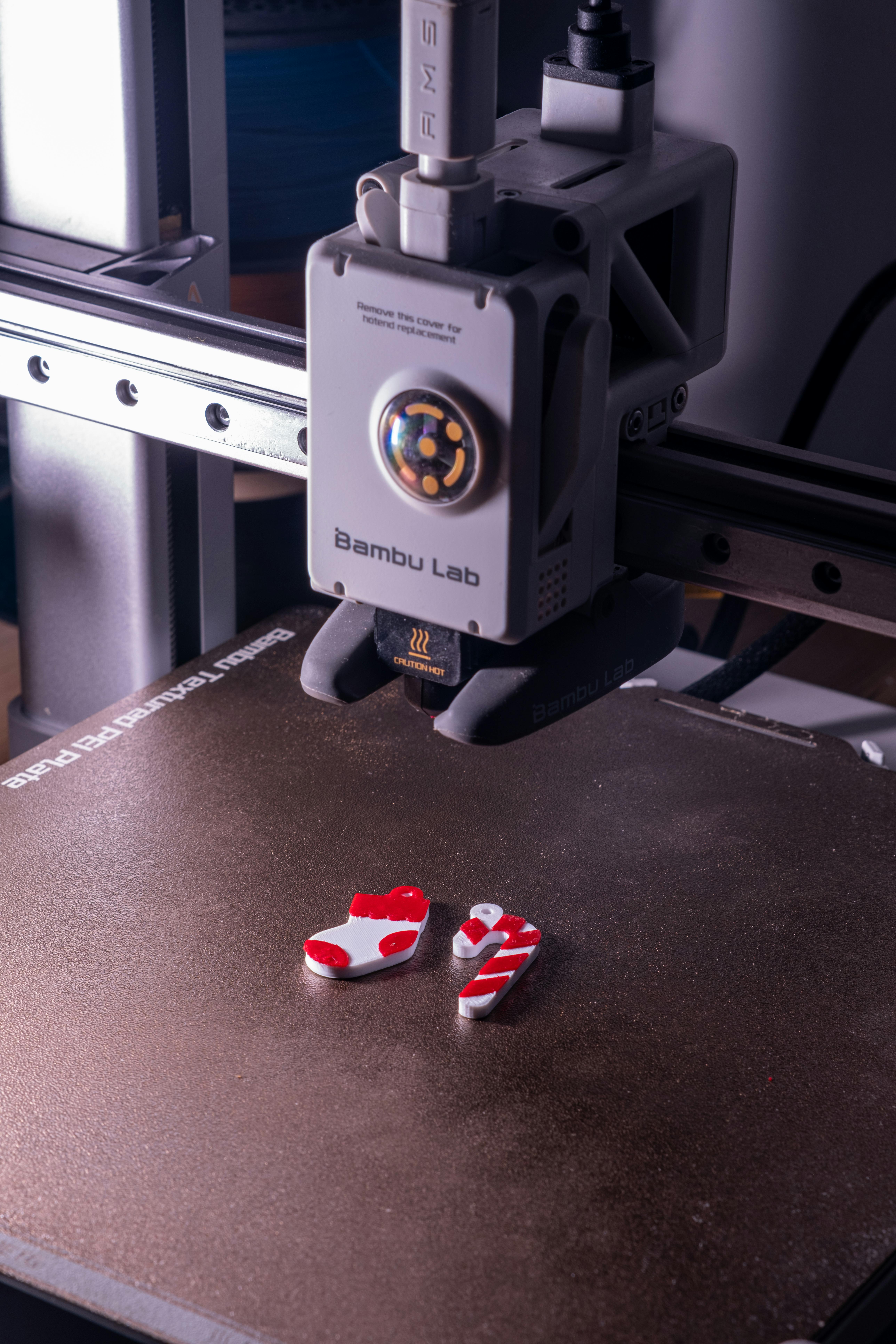
MJF's native surface is dark grey with a slightly powdery feel due to residual fusing agent. Blasting removes this powdery feel and is the standard surface for almost all shipped parts. Following are three post-processing routes that can cover most mass production needs in the market by 2026.
| Surface | Process | Appearance | Best Use |
|---|---|---|---|
| Standard Blasting | Glass beads 15–25 seconds | Matte dark grey | Fit and functional default |
| Black Dyeing | Vapor / Dip Dyeing | Saturated pure black | Consumer product housings |
| Vapor Polishing | PostPro / AMT Chemical | Smooth, Ra < 2 µm | Sealing surfaces, medical |
| Graphite Polishing | Manual Graphite | Gunmetal metallic sheen | Small batch aesthetic covers |
| Conductive Plating | Nickel-copper spray 25 µm | Silver, 60 dB shielding | EMI / ESD enclosures |
Why MJF is Most Cost-Effective for 50–2,000 Pieces
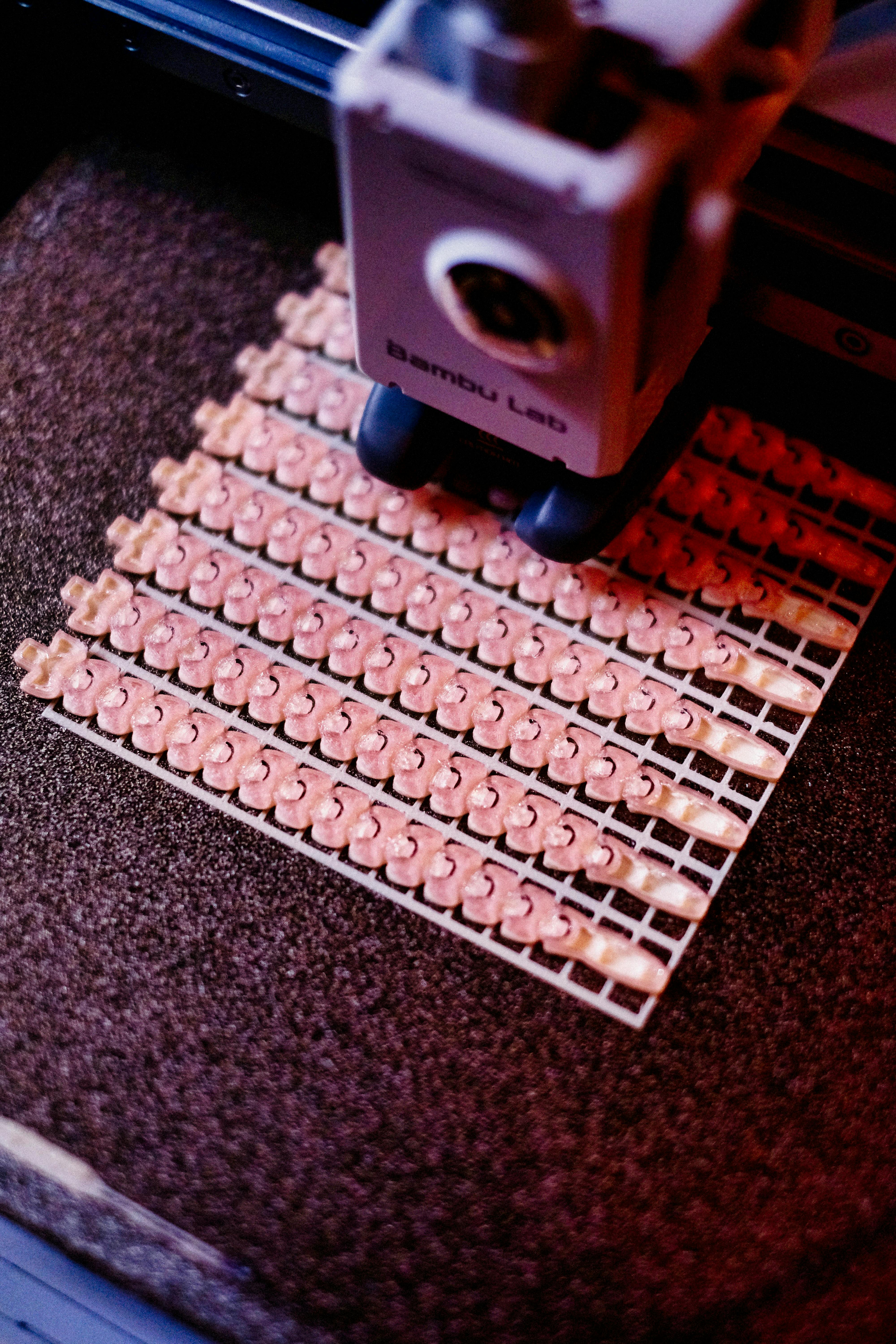
The effective build area for HP 5200 is 380 × 284 × 380 mm. Since unfused powder acts as its own support, packing density can typically reach 10–12% of the volume—about 40 times the support volume of SLA. This means hundreds of small parts can be vertically packed in each build, driving down machine time per piece to extremely low levels.
| Quantity | Unit Cost (PA12, 40 cm³) | Compared to Injection Molding | Lead Time |
|---|---|---|---|
| 1–10 pieces | US$32 | −96% | 3 days |
| 50 pieces | US$14 | −82% | 5 days |
| 500 pieces | US$8.20 | Breakeven with tooling | 7 days |
| 2,000 pieces | US$7.40 | Tooling amortization wins | 10 days |
| 10,000 pieces | US$7.10 | Recommend switching to injection molding | 14 days |
Three Case Studies of Functional Parts Currently Dominated by MJF
Case 1 — Quadcopter Drone Body with Integrated Antenna Waveguide
A drone manufacturer in Shenzhen replaced a five-piece CNC aluminum casing with a unibody MJF PA12 body. The new part weighs 112 g (original 184 g) and passed MIL-STD-810G 514.8 vibration profile for 200 hours without failure; the antenna waveguide integrated into the body reduced signal loss from −8.2 dB to −6.7 dB.
Key design action: Route the antenna waveguide along the build's X-axis instead of the Z-axis, placing the 11 µm rough surface on the non-radiating interior, with the smoother side facing the RF path.
Case 2 — ESD-Safe Electronic Carrier for Semiconductor Handling
A wafer handling OEM used PA12 Glass Beads with a 25 µm nickel-copper conductive plating, reducing surface resistance to 10⁶ Ω, meeting ANSI/ESD S20.20 requirements for Class 0 component static protection. Each carrier had 28 component contact points, with no static damage incidents after 100,000 wafer handling cycles.
Case 3 — PA12 FR V-0 Connector Housing for Railway Signals
PA12 FR passed UL 94 V-0 and EN 45545-2 HL2 at 1.6 mm thickness. MJF allowed the team to ship 900 connector housings in 12 days, 8 weeks ahead of the original injection molding solution, ensuring on-time delivery of train cars.
Do's and Don'ts Overview
| Do | Don't |
|---|---|
| Default wall thickness to 1.0 mm | Copy SLA's 0.6 mm |
| Add a 4 mm powder removal hole for every enclosed cavity | Leave enclosed internal lattices without an exit |
| Orient snap-fits so force is in XY | Allow cantilevers to stack along the Z direction |
| Quote with blasting as the baseline | Assume parts can be painted directly after powder removal |
| Choose PA11 when elongation at break > 25% | Default to PA12 for all projects |
Common Design Mistakes in 2026
| Mistake | Consequence | Correction |
|---|---|---|
| Uniform 3 mm wall thickness throughout | Shrinkage, 12 hours cooling | Hollow out to 1.5 mm with ribs |
| Ignoring PA12's 1.3% moisture absorption | Hole diameter shrinks 0.1 mm after one week | Dry critical holes or apply coating |
| Specifying bright white surface | MJF has no such option | Change to black dyeing or vapor polishing |
| Tall, slender parts oriented vertically | Z-direction warping, blasting damage | Lay flat or tilt 15° |
| Using PA12 FR for outdoor UV | Flame retardant degrades under UV | Switch to PA11 + UV coating |
Pre-Build Checklist
- All wall thicknesses ≥ 1.0 mm, hollow where possible
- At least one 4 mm powder removal hole for every enclosed cavity
- Clearance for moving parts 0.4 mm (0.5 mm for PA11)
- Allow +0.2 mm machining allowance for critical hole diameters
- Orient snap-fits so elastic deformation occurs in XY, not along Z
- Select material based on environmental conditions (moisture absorption, UV, flame retardant, ESD)
- Clearly specify surface finish: blasting / dyeing / polishing / plating
- Compare against injection molding break-even points for quantity ranges
Design Considerations
MJF is no longer a "near-production" process. With 1.01 g/cm³ density, nearly isotropic tensile strength, six mass-production grade polymers, and a complete post-processing chain—as long as you design with its native surface in mind, adhere to 1.0 mm / 4 mm powder removal holes, and orient snap-fits in XY, your 3D printed part will be a no-nonsense engineering component.


0 comments