
A six-pin connector in a wiring harness next to an exhaust pipe deformed and shorted at 175°C—even though its datasheet HDT was 220°C. Purchasing mistakenly equated HDT with continuous use temperature. This is incorrect. HDT is a 30-minute short-term test under a 0.45 or 1.8 MPa flexural load; this connector, however, endured 1,200 hours of static stress, fuel vapors, and thermal cycling. The polymer crept to failure long before the datasheet number became relevant.
Failure in selecting heat-resistant polymers is often due to misinterpreting data rather than choosing the wrong family. Glass Transition Temperature (Tg), Heat Deflection Temperature (HDT), Vicat Softening Point, and Continuous Use Temperature (CSUT) each describe different phenomena. Buying PEEK when PPS suffices is wasteful; buying PA66-GF when PEI is needed is dangerous. This guide dissects the data, categorizes material families, and walks through three real-world specification cases.
What Each Temperature Datum Truly Predicts
Confusing these four metrics is the most common root cause of thermal failure in plastic parts. Each is measured under specific load, time, and deformation criteria, and predicts different failure modes.
| Metric | Measured Content | Typical Load | Predicted In-Service Failure |
|---|---|---|---|
| HDT (0.45/1.8 MPa) | Deflection of 0.25 mm under fixed load | 0.45 or 1.8 MPa | Short-term loss of stiffness under flexure |
| Vicat Softening | 1 mm probe penetration | 10 or 50 N | Surface softening, low-stress dimensional drift |
| Tg (DMA, DSC) | Onset of amorphous chain segment motion | Near zero | Modulus drop, accelerated creep |
| CSUT / RTI | Half-life of critical properties at 20,000 hours | Application-dependent | Upper limit for long-term load-bearing service |
| Short-term Peak | Survival without permanent changes | Thermal stress only | Reflow soldering, paint baking, autoclave cycles |
Rule of thumb: Amorphous polymers for continuous service should be at least 20°C below Tg; semi-crystalline polymers below CSUT (not HDT). HDT is only a relative ranking tool among candidate grades and should never be used as a service limit.
Overview of High-Temperature Polymer Families
The table below covers the ten major families used in almost all thermally driven specifications above 130°C. Costs are benchmarked against unfilled PA66 = 1.0× spot price in Q1 2026; filled grades amplify both stiffness and price.
| Polymer | HDT @1.8 MPa (°C) | CSUT (°C) | Tensile Strength (MPa) | Cost (×PA66) |
|---|---|---|---|---|
| PEEK (Unfilled) | 152 | 260 | 100 | 60–90 |
| PEEK 30% Carbon Fiber | 315 | 260 | 230 | 90–130 |
| PEKK | 160 | 260 | 105 | 70–100 |
| PEI (Ultem 1000) | 200 | 170 | 105 | 12–18 |
| PPS (40% Glass Fiber) | 265 | 220 | 165 | 8–14 |
| PSU (Udel) | 174 | 150 | 70 | 10–15 |
| PPSU (Radel) | 207 | 180 | 70 | 15–22 |
| LCP (Vectra) | 240 | 220 | 180 | 10–18 |
| PAI (Torlon) | 278 | 260 | 190 | 70–110 |
| PTFE / FEP | 55 / 70 | 260 / 200 | 25 / 22 | 20–35 |
Note the HDT vs. CSUT discrepancy for PEEK and PTFE: high-melting semi-crystalline polymers, even with low HDT, can allow for long-term high-temperature service because creep is dominated by crystallinity, not the amorphous fraction.
Cost Ladder Corresponds to Operating Temperature Ranges
Cost-driven over-specification is wasteful but easily corrected; cost-driven under-specification is dangerous and often undetected until field returns. Use this ladder to define a shortlist of candidates before consulting datasheets.
| Operating Range | Preferred Family | Secondary | Relative Cost |
|---|---|---|---|
| Below 100°C | PA66, PC, ABS | PBT | 1.0–2.0× |
| 100–130°C | PA66-GF, PBT-GF | PPO/PPE | 1.5–3.0× |
| 130–170°C | PSU, PPSU | PA46-GF | 8–22× |
| 170–220°C | PEI, PPS-GF, LCP | PPSU | 8–22× |
| 220–260°C | PEEK, PEKK, PAI | LCP, PPS | 60–110× |
| Above 260°C | PAI, PEEK-CF, PTFE (low load) | Polyimides | 70–130× |
Glass Fiber and Carbon Fiber: How Fillers Elevate HDT

Adding 30–40% glass or carbon fiber to semi-crystalline matrices can increase HDT by 80–150°C—but has limited impact on CSUT, typically only 10–20°C. Fillers support the amorphous phase under short-term loads but do not alter polymer chemistry, oxidation kinetics, or creep mechanisms. A 30% glass-filled PA66 with an HDT of 250°C still only has an RTI of about 130°C.
Carbon fibers further provide stiffness and dimensional stability under heat, and also impart thermal conductivity, aiding heat dissipation in connector pins and gear teeth. The trade-offs are anisotropy, weld line weakening, and wear against metal mating surfaces.
Processing and Molding Considerations
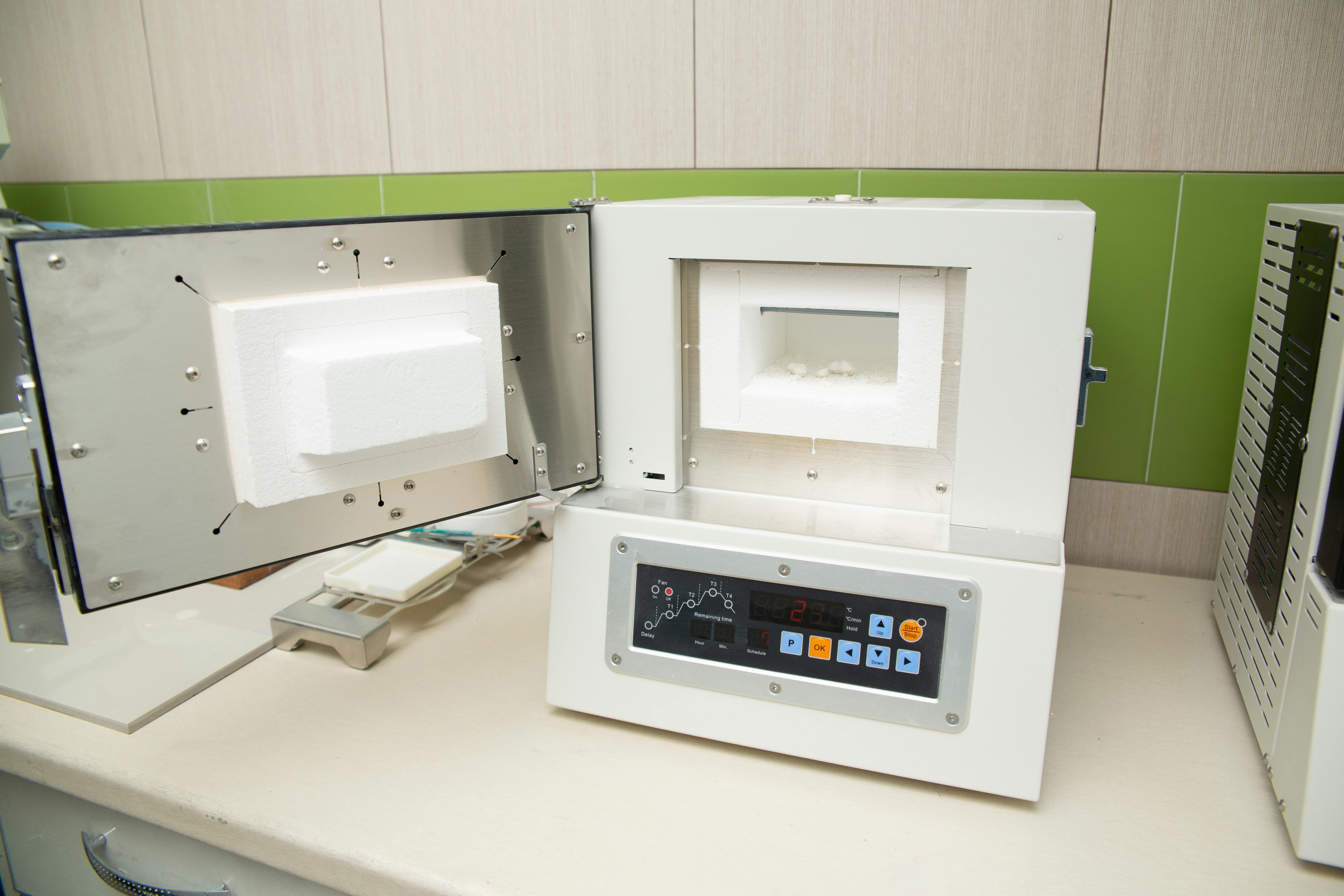
High-temperature polymers demand a lot from molding machines. PEEK, PEKK, PAI require barrel temperatures above 360°C, appropriately specified hot runners, and hardened gate tooling. PPS and LCP flow well but are prone to flash into 5 µm parting lines. PEI and PSU are easy to mold with standard hot runner systems, but require thorough drying—PEI absorbs enough moisture in 4 hours of open storage to cause splay marks in every shot.
For 3D printing, PEEK and PEI require actively heated chambers above 130°C and bed temperatures of about 230°C to control crystallization and warping. PEEK and PEKK must be annealed post-printing to achieve full crystallinity, which can improve tensile strength by 20–40%.
Applications and Case Studies
The following three real-world specifications demonstrate how metrics, families, and the cost ladder integrate into defensible material selection decisions.
Case 1: Engine Compartment Connector Body, 165°C Continuous
Specification: USCAR-2 Class 4, 165°C continuous, up to 200°C for 1,000 hours, vibration to 30 g, exposure to oil mist and glycol. Initial selection: PA66-GF35—rejected due to an RTI of only 130°C, and oil aging degrading the glass-resin coupling within 500 hours. Final selection: PPS 40% glass fiber + elastomer toughened. HDT of 265°C provided margin for 200°C excursions; CSUT of 220°C covered 165°C continuous; inherent chemical resistance to glycol. A 4x cost premium over PA66-GF, but field return rate dropped from 1.8% to below 0.05%.
Case 2: Sterilizable Surgical Tray Handle, 1,000 Autoclave Cycles
Specification: 134°C, 100% steam, 30 min per cycle, 1,000 cycles, mechanical impact, gamma resistance. Required Tg above 180°C to prevent hydrolytic creep. Tested PSU showed stress cracking after chlorhexidine wipes; PEI discolored under gamma radiation. Final selection: PPSU (Radel R-5500): Tg of 220°C, amber transparent, validated for 1,500+ sterilization cycles, resistant to disinfectants and 50 kGy gamma radiation. Cost was 18 times that of PA66, but part life now exceeds instrument life, eliminating field replacements.
Case 3: Jet Engine Cabin Interior Bracket, FAR 25.853 Compliant
Specification: 130°C continuous, 180°C peak, 60-second flame test to FAR 25.853, peak heat release ≤ 65 kW/m², low smoke and toxicity (FST), weight-critical. Final selection: PEI (Ultem 9085)—inherently flame retardant without additives, meets FAR 25.853 (a) and (d), FST data within Boeing BSS 7239 / Airbus ABD 0031 limits, FDM printable in heated chamber. Carbon fiber-filled PEI achieved 28% weight reduction over aluminum, and passed all thermal and FST requirements.
Do's / Don'ts
| Do | Don't |
|---|---|
| Set continuous service limits using CSUT or RTI | Use HDT as an operating temperature limit |
| Validate with actual chemical environment, not just thermal load | Assume heat resistance implies chemical resistance |
| Use amorphous load-bearing parts at least 20°C below Tg | Subject amorphous polymers to sustained stress above Tg |
| Anneal PEEK / PEKK after printing to achieve crystallinity | Ship printed parts directly and rely on datasheet strength |
| Specify filler orientation near weld lines | Ignore strength reduction at weld lines for filled grades |
Common Mistakes
| Mistake | Why it Fails | Correct Approach |
|---|---|---|
| Material selection based solely on HDT | 30-minute flexural test, not creep resistance | Match CSUT to application's duty cycle |
| Treating glass fiber filling as a heat resistance upgrade | RTI only increases by 10–20°C | Base the upper limit on the base resin chemistry |
| Ignoring moisture drying for PEI / PSU | Splay, voids, weld line failure | Dry to <0.02% before molding |
| Over-specifying PEEK for 150°C applications | 60x cost is unnecessary | PEI or PPSU are usually sufficient |
| Printing PEEK without annealing | Amorphous skin, lower strength | Anneal with ramp from 150°C to 200°C and hold |
| Using PTFE for structural load-bearing | Cold flow, low modulus | Only for seals, liners, sliding applications |
Pre-Selection Checklist
Go through this checklist before committing to a polymer family. A 30-minute review can save weeks of qualification rework and avoid the most common thermally-driven field failures. Document it and circulate it to electrical, mechanical, and supply chain stakeholders before consulting datasheets.
- Continuous operating temperature 95th percentile and confidence interval
- Peak excursion temperature, frequency, and duration per cycle
- Sustained mechanical load (MPa) at peak temperature, including bolt pre-load and snap-fit retention
- Chemical exposure list: fluids, vapors, cleaning agents, and frequency
- Regulatory requirements: UL 94, FAR 25.853, USP Class VI, ISO 10993, RoHS / REACH
- Lifetime target (hours) and number of thermal cycles
- Manufacturing route: injection molding, machining, FDM, SLS—each limits available families
- Tolerance for color shift, surface gloss degradation, and lifetime dimensional drift
Design Takeaways
Heat-resistant polymer selection rewards designers who treat datasheet numbers as vocabulary, not verdicts. HDT is for ranking candidates within the same class; CSUT sets operating limits; amorphous load-bearing parts are limited by Tg minus 20°C. Pay the PEEK or PAI premium only for 220°C continuous, aggressive chemical, or extreme creep resistance needs; for the broad 150–200°C range, PPS, PEI, and PPSU often win on cost. Validate with the real environment—heat, chemistry, and load in tandem—and anneal or dry based on chemical properties. The connector that melted at 175°C didn't need exotic chemistry; it needed an engineer who read CSUT, not HDT.


0 comments