
A titanium bracket broke free from the build plate at 14mm height: support strategy used minimal contact teeth for a 35-degree overhang, the recoater blade scraped a warped edge, and the laser planed three layers of misaligned powder bed before the operator stopped the machine. This geometry is theoretically printable, but the support design and orientation are not. DMLS failures rarely look like CAD problems; they look like thermal, mechanical, and powder flow problems that designers can solve upstream.
Why DMLS Design is Different
DMLS melts metal powder layer by layer with a focused laser in an inert atmosphere. Each layer cools at hundreds of degrees per second, locking residual stresses into the structure as the part grows. Designing for DMLS means treating the build as a thermomechanical event, not just a geometric projection. Wall thickness, overhang angles, support density, orientation, and machining allowance all interact with the thermal path.
This guide focuses on DfAM practices specific to powder bed fusion metals: alloy-dependent minimum features, support design, build plate adhesion, recoater clearance, and nesting. For the mindset shift towards part consolidation, see the redefining-metal-part-design article; for heat treatment, HIP, and surface post-processing, see the post-processing guide.
Alloy-Dependent Minimum Features
Each alloy in the DMLS process has its own laser absorptivity, melt pool dynamics, and shrinkage behavior. A 0.4mm wall that prints smoothly on AlSi10Mg will warp in Inconel 718 and crack in copper. The table below lists practical baselines for a production window; prototypes can be more aggressive, but expect more support and orientation penalties.
| Alloy | Min Wall Thickness (mm) | Min Hole Diameter (mm) | Self-Supporting Angle | Max Unsupported Overhang |
|---|---|---|---|---|
| AlSi10Mg | 0.4 | 0.5 | 45 degrees | 1.0mm |
| Ti6Al4V | 0.4 | 0.6 | 40 degrees | 0.8mm |
| Inconel 718 | 0.5 | 0.7 | 45 degrees | 0.6mm |
| 17-4PH Stainless Steel | 0.5 | 0.6 | 45 degrees | 1.0mm |
| CoCr | 0.5 | 0.7 | 40 degrees | 0.6mm |
| Pure Copper | 0.8 | 1.0 | 50 degrees | 0.4mm |
Key Design Action: Lock in the alloy before finalizing geometry. A bracket designed with 0.4mm walls and 40-degree overhangs is an aluminum part; switching to Inconel mid-project will force a CAD redraw, not just a parameter change. At the moment of material selection, tag every wall, hole, and overhang with the budgeted value for that alloy.
Support Design: Solid, Block, Lattice
Supports do four things: anchor the part to the build plate, wick heat away from downward-facing surfaces, resist recoater blade forces, and resist thermal distortion. Choosing the wrong type wastes powder and machine time; choosing the right type often saves more material than the supports themselves.
| Type | When to Use | Contact Density | Removal Method |
|---|---|---|---|
| Solid Block | Build plate interface, high stress areas | Continuous | Bandsaw + Machining |
| Teeth/Conical | Downward-facing aesthetic surfaces | 0.5-1.0mm spacing | Break-off + Grinding |
| Lattice (Gyroid) | Heat dissipation under thin walls | 30-50% volume | CNC or Wire EDM |
| Tree/Branch | Internal overhangs, channels | Sparse | Manual + Bead Blasting |
| Volume Supports | Large cross-sections, cooling | Fully filled | Machining only |
Support placement and removal path must be planned simultaneously. A lattice that perfectly conducts heat but requires a 5-axis mill to reach is a cost trap. Tag each support contact face as manually accessible, CNC accessible, or sacrificial; the latter should place support faces on surfaces that will be removed by final machining.
Orientation: Recoater Blade, Stress, Downward-facing Surfaces
Orientation determines which faces become downward-facing (rough), which faces bear loads along the build direction (Z-direction is weakest), and whether the recoater blade encounters long straight edges or gentle curves. Incorrect orientation can double support volume and triple post-processing time.
| Consideration | Rule of Thumb | Consequence of Violation |
|---|---|---|
| Recoater blade collision | Long edges angled 5-15 degrees from recoater axis | Edge warping, blade crash, build abort |
| Stress axis | Main load axis 0-30 degrees from Z-direction | Layer line fatigue cracks |
| Downward-facing limits | Critical surfaces kept above 45 degrees | Drossing, Ra > 20um, support scars |
| Thermal mass | Thick sections offset in Z-direction | Warping, build plate detachment |
| Powder egress | All internal channels sloped >5 degrees | Residual sintered powder |
Feature-Based Machining Allowance
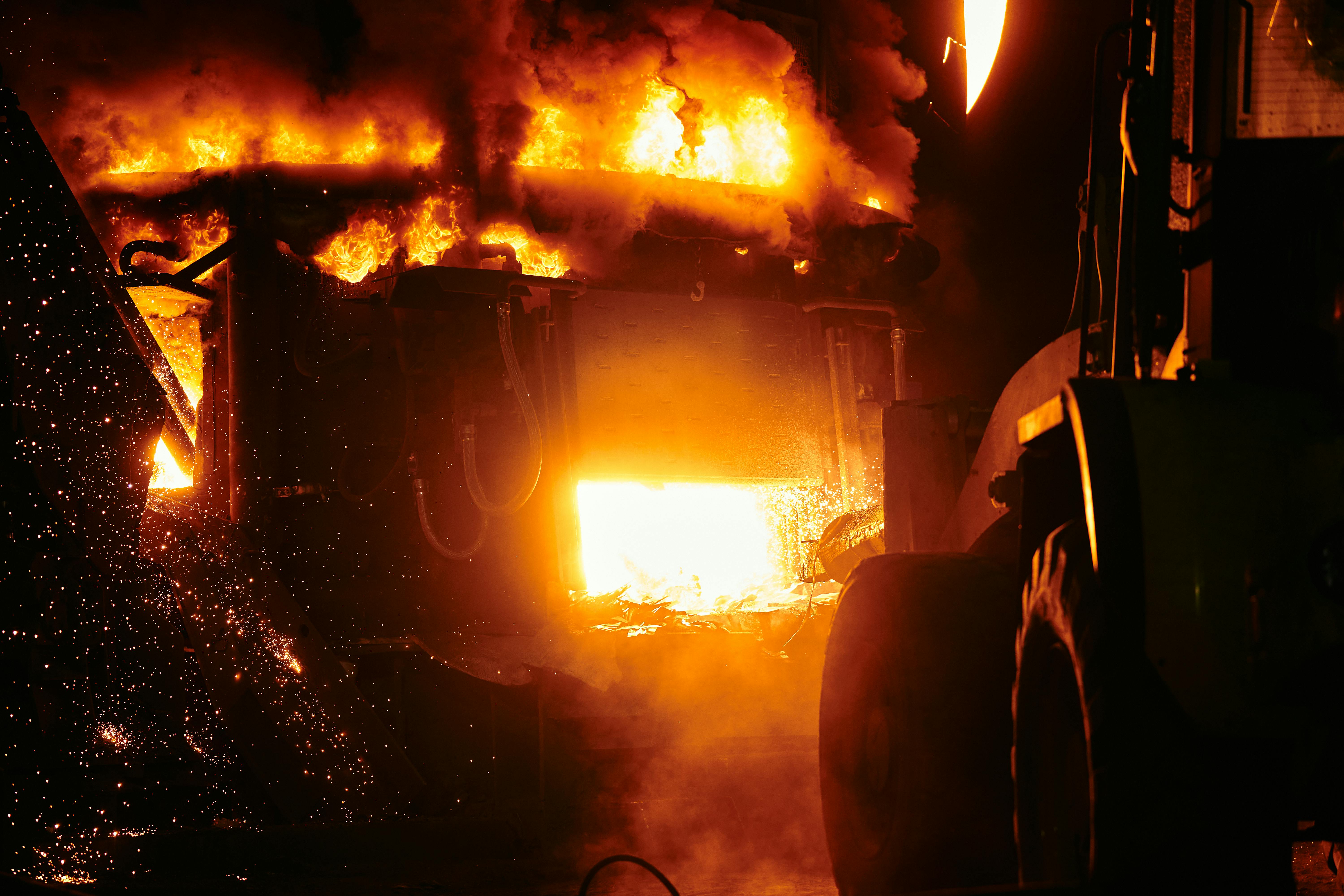
DMLS prints Ra 6-12um directly; bearing surfaces, sealing surfaces, and threaded holes require machining. In CAD, add allowance with offset bodies to track the printed shape, HIP'd shape, and machined shape states.
| Feature | Unilateral Allowance (mm) | Reason |
|---|---|---|
| Bearing Bore H7 | 0.5 | HIP shrinkage, then re-round |
| Sealing Face | 0.3 | Target Ra 0.8 |
| Threaded Hole | Solid for drill/tap | Avoid printed thread fatigue |
| Datum Surface | 0.4 | Establish before HIP |
| Mating Flange | 0.5 | Flatness < 0.05mm |
| Aesthetic Only | 0.2 or 0 | Bead blasting acceptable |
Powder Handling and Inert Atmosphere
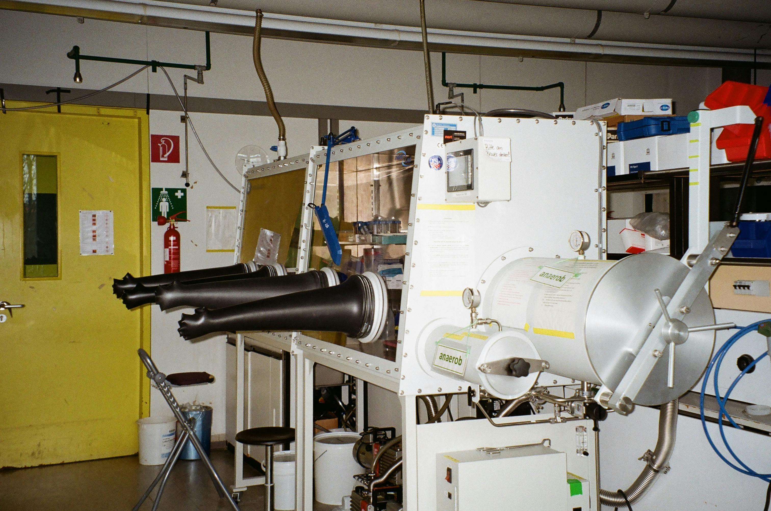
Titanium and aluminum powders below 25um are explosive; nickel powders pose inhalation risks. Production lines control argon oxygen content to <100ppm during builds and use enclosed recirculating sieving stations. Designers can reduce operator safety exposure by reducing powder trapping pockets and tagging regions with high powder retention risk.
Every internal cavity requires at least two openings: one for unmelted powder to flow out, and one to confirm the cavity is clean. A single powder egress hole will retain powder, becoming a contamination risk for medical or aerospace acceptance.
Applications and Case Studies
The three cases below demonstrate DfAM-for-DMLS choices, distinct from the part consolidation mindset and post-processing chain discussed in companion articles. Each case focuses on support, orientation, and feature decisions that made the build viable.
Aerospace Fuel Nozzle: Self-Supporting Swirl Channels
An Inconel 718 nozzle with six tangential swirl channels was redesigned so that each channel's apex remained above 47 degrees—two degrees above the alloy's self-supporting limit. Build time decreased from 38 hours with internal supports to 24 hours without supports, and post-processing time dropped from 6 hours to 1.5 hours.
Medical Ti6Al4V Implant: Lattice Surface with Solid Core
A spinal fusion cage used a 600um octet-truss lattice on bone-contacting surfaces to promote osseointegration, with a 1.2mm solid core for fatigue strength. Orientation placed the lattice at 50 degrees downwards, allowing the lattice struts to be self-supporting without adding supports within the micron-scale porous structure.
Heat Exchanger Tube Bundle: Nesting and Recoater Strategy
A 17-4PH counterflow heat exchanger with 64 tubes was nested in four staggered rows, angled 12 degrees from the recoater axis. The tilt prevented the recoater blade from resonating across long, flat tube tops and allowed each tube to provide self-support for adjacent tubes, reducing support volume by 61%.
Do's and Don'ts
| Do | Don't |
|---|---|
| Lock in alloy before finalizing design | Treat alloy as interchangeable later |
| Angle long edges from recoater axis | Orient flat tops parallel to recoater |
| At least two holes per cavity | Only one powder egress hole |
| Plan support removal paths | Place lattices where tools can't reach |
| Add allowance for bearing and sealing surfaces | Trust direct printed Ra |
| Offset thick sections in Z-direction | Concentrate thermal mass in one slice |
Common Mistakes
| Mistake | Symptom | Correction |
|---|---|---|
| Overhang at alloy limit | Drossing, support scars | Add 5-degree buffer |
| Single powder egress hole | QA rejection due to residual powder | Add a second vent hole |
| Planes parallel to recoater axis | Edge warping, build abort | Tilt 5-15 degrees |
| Lattice without removal path | Post-processing cost overrun | Change to tree supports or reorient |
| H7 without machining allowance | Out-of-tolerance bore | Add 0.5mm offset body in CAD |
| Stacked thermal mass | Build plate detachment mid-build | Stagger or split build |
Pre-Build Checklist
- Alloy locked in and tagged on every wall, hole, and overhang
- All overhangs are 5+ degrees above alloy self-supporting angle
- Long edges angled 5-15 degrees from recoater axis
- Every internal cavity has at least two tagged openings
- Support type selected per region, removal path validated
- H7, sealing, and datum surfaces have machining allowance via offset bodies
- Thermal mass staggered in Z-direction; no single thick slice
- Powder flush and inspection plan included in build file
Key Takeaways
DMLS rewards designers who treat the build as a thermal event plus a recoater blade. Alloy dictates minimum features, orientation determines support volume and surface finish, and cavity strategy dictates QA pass rates. Get these three right, and the geometry will follow.
The pre-build checklist above is the shortest version of this guide. If any item on the list fails, the print will tell you—often loudly, sometimes at 14mm into a 200mm build. Catching these at the CAD stage saves build time and material far exceeding the cost of an extra design review.


0 comments