
A set of PA12 GF printed assembly jigs for a 14-station PCB production line replaced the original aluminum alloy CNC fixtures that cost $3,800 and took 18 working days. The printed version delivered in 4 days, cost $420 per unit, was 52% lighter, and absorbed three design revisions during the process without rework. Approximately 9 times cheaper, 4 times faster, and tolerant of frequent revisions, this gap is why additive manufacturing has become the default process for jigs and fixtures on low-volume production lines with 5 to 50 parts per SKU.
Jigs and fixtures are not products; they are process infrastructure. They exist solely to make a specific task faster, safer, or more repeatable, and must withstand gloves, grease, impacts, cleaning cycles, and operators always using them harder than CAD load assumptions. A jig that is perfect in CAD but falls apart on the production line after a month is no better than an expensive CNC version—it just makes waste happen faster.
This guide breaks the problem down into five layers: classification (what type of tool you are making), material selection, DFM numbers in real-world conditions, hybrid integration with traditional hardware, and validated case paradigms. Each section is written with the goal that "designers can directly pull numbers into CAD without deriving them from scratch."
Differences Between Jigs, Fixtures, and Gauges
These three terms are often used interchangeably on the shop floor, but their tolerance budgets, materials, and service life requirements are completely different. Misclassifying a tool is the most common reason for disappointment with printed auxiliary tools on the production line: making a fixture with jig tolerances results in daily realignments; applying a fixture's service life budget to a gauge that actually needs weekly calibration results in untraceable deviations.
| Tool Type | Function | Typical Tolerance | Typical Service Life |
|---|---|---|---|
| Jig | Guides tools or machining actions (drilling, trimming, bonding) | ±0.10–0.20 mm | 3–12 months, 5k–50k cycles |
| Fixture | Holds or positions parts during operation | ±0.20–0.50 mm | 6–24 months, 10k–100k cycles |
| Gauge | Verifies part dimensions pass/fail | ±0.05 mm or tighter | Until calibration drift, recalibrate every 6–12 months |
| Soft Jaws / Nests | Protects part surfaces during clamping | ±0.30 mm | Consumable, replaced as worn |
Material Selection for Printed Jigs
SLS/MJF PA12 GF is the primary material for about 70% of printed production tooling because it balances rigidity, steady-state dimensional stability, and cost. However, material selection should follow the load scenario, not the factory default.
| Material | Rigidity (Flexural Modulus) | Relative Cost | Durability / Best Use |
|---|---|---|---|
| PA12 GF (SLS/MJF) | 3,000–3,500 MPa | 1.0x (baseline) | General fixtures, nests, positioning bodies |
| Mineral-filled PA | 2,500–3,000 MPa | 0.9x | Large volume bodies, cost-sensitive scenarios |
| CF-PA12 / CF-PA6 | 6,000–8,000 MPa | 1.6–2.0x | High-rigidity cantilevers, overhanging positioning |
| Metal-filled PA (316L filled) | 4,000–5,000 MPa | 1.8x | Wear pads, drill guide bodies |
| 6061 Aluminum CNC | 68,900 MPa | 3–10x | Master gauges, tooling for over 100k cycles |
In electronic assembly scenarios, any fixture that touches unencapsulated circuit boards must use an ESD-safe PA12 variant (surface resistivity 10^6–10^9 Ω); this adds about 15–20% to the cost compared to standard PA12, but eliminates external failures caused by static electricity accumulation and is a mandatory specification in most electronic contract manufacturing environments.
DFM Numbers in Real-World Conditions
The following numbers determine whether a fixture is good on day one or discarded after one shift. These numbers account for gloves, fatigue, part tolerance variations, and operators always using them harder than CAD load assumptions.
| Feature | Recommended Size | Reason |
|---|---|---|
| Handle Diameter | 28–35 mm | Easy to grip even with nitrile gloves |
| Finger Recess Depth | ≥12 mm | Allows full fingertip grip |
| Test Part Periphery Clearance | 0.25–0.40 mm per side | Absorbs part tolerance and thermal expansion |
| Clamping Threaded Posts | M5 steel insert + 3 mm wall thickness | Printed threads strip after 500 cycles |
| Base Mounting Posts | M6, 4 mm wall thickness, 15 mm depth | Withstands lateral loads |
| Visual Pass/Fail Step | ≥1.5 mm | Clearly visible under factory lighting |
| Impact Edge Fillet | R ≥ 3 mm | Withstands 1 m drop from desktop |
Why Additive Manufacturing Outperforms Aluminum CNC for Low Volume
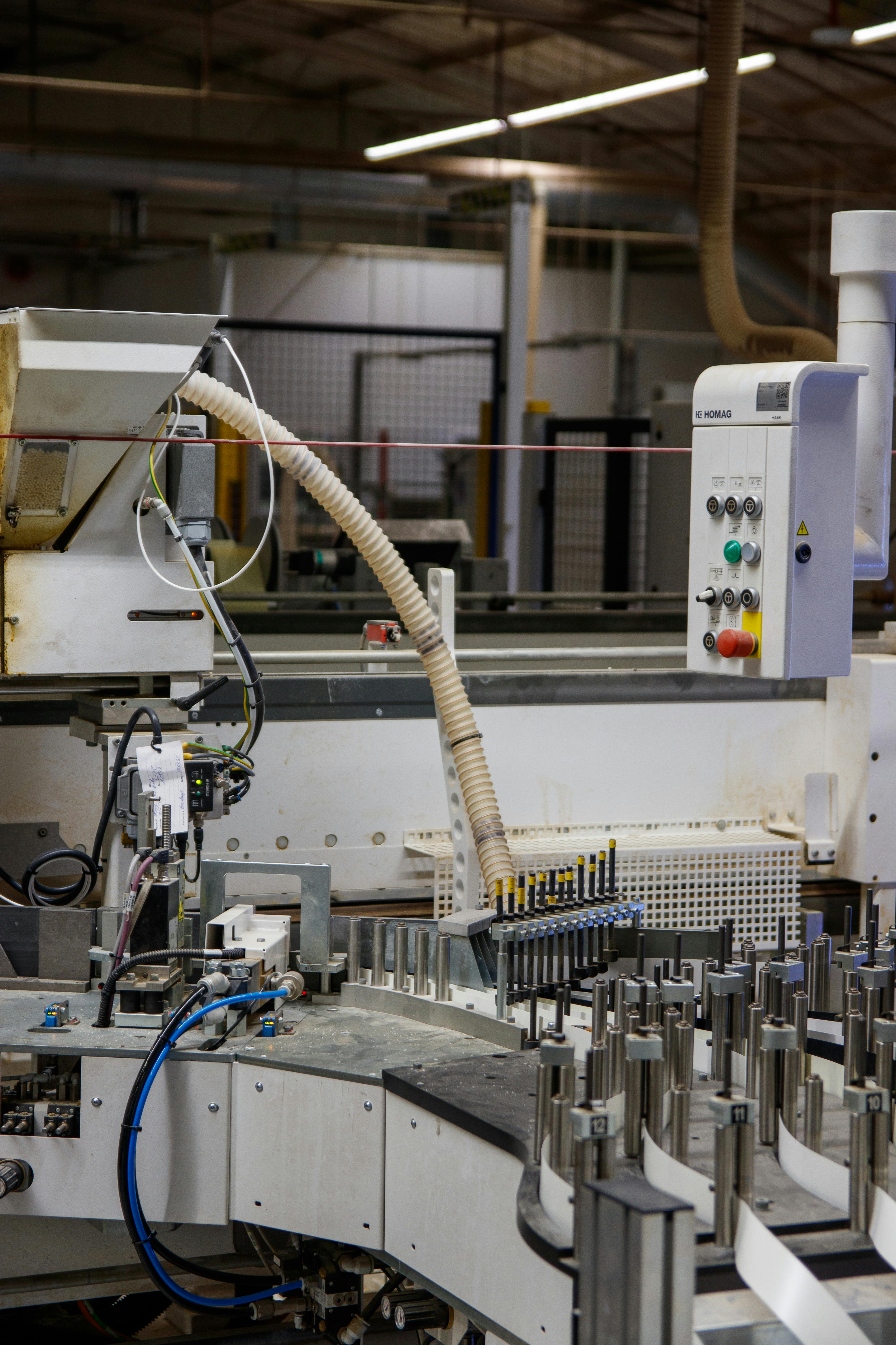
For quantities under approximately 50 parts per SKU, aluminum CNC comes with fixed costs that additive manufacturing fundamentally lacks: programming (2–6 hours), raw material clamping, first article inspection, and minimum order fees from machine shops. When tools require frequent revisions (fixtures need to be modified for each design iteration), these fixed costs accumulate into a significant drain on the production budget.
Geometric freedom is the second advantage. Printed fixtures can enclose complex parts, integrate wiring channels, conceal sensor wires, and incorporate conformal cooling or vacuum channels without additional processes. Aluminum CNC either requires multi-axis machines or parts are disassembled and reassembled, both of which significantly drive up costs and lead times.
Integrating Sensors, Inserts, and Standard Hardware
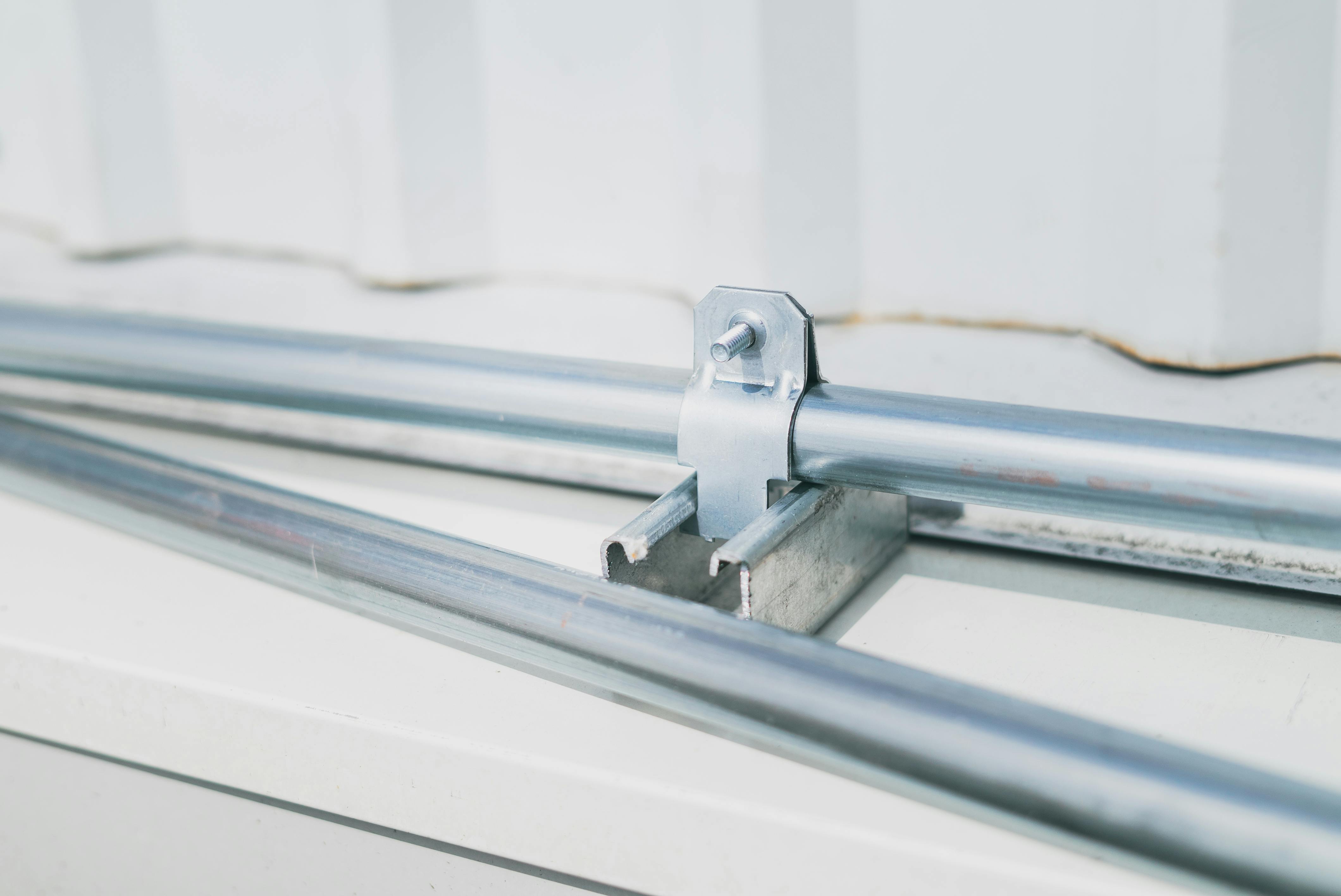
Printed fixtures should treat the printed plastic as the structure and standard hardware as the interface. Brass heat-set inserts (M3–M8) pressed in with a 280°C soldering iron provide threads more durable than the fixture body; press-fit steel dowel pins can achieve positioning accuracy of ±0.05 mm, far exceeding the ±0.25 mm capability of SLS.
In PCB assembly scenarios, integrated LEDs can be powered by PoE switches and driven by the MES system, illuminating the next component's location cycle by cycle; the fixture thus transforms from a mere carrier into a display interface, and operator error rates typically decrease by over 60%.
Application Scenarios and Validated Case Paradigms
Case 1 — PCB Assembly Fixture with Integrated LED Guidance
A contract manufacturer replaced machined versions costing $2,100 each with a 14-day lead time, with ESD-safe PA12 GF printed jigs costing $310 each and a 5-day lead time for 24 consumer electronics PCB production lines. Number of revisions in the first month: 7 (frequent engineering changes), with each revision shipped in < 24 hours, cumulative revision cost of USD 880; with CNC versions, the same 7 revisions would cost a minimum of USD 8,400.
Key design actions: Entire part made of ESD-safe PA12 GF; all mounting points use M3 brass heat-set inserts; light guide channels printed with 3.5 mm diameter and bead-blasted interior walls for uniform diffusion; connector holes left with 0.4 mm clearance per side.
Case 2 — Drilling Jig with Hardened Steel Bushings
An aerospace repair facility replaced a $5,400 CNC aluminum drilling jig with a printed PA12 GF body incorporating press-fit hardened steel drill bushings; the body cost $380, and four bushings totaled $48. The jig body remained intact after 4,000 drilling cycles, the bushings showed wear, and after replacing a set of steel bushings (USD 12), it continued to serve. Total cost: USD 494 vs USD 5,400 for equivalent function over a 7-year maintenance period.
Case 3 — Gauge Replacing $8,000 Machined Master Part
A Tier 2 automotive supplier needed a pass/fail gauge for plastic buckles; the traditional hardened steel master part was quoted at $8,200 with a 6-week lead time. They switched to a printed CF-PA12 gauge with three press-fit locating pins, delivered in 8 days for USD 580, recalibrated every 6 months using a printed reference part. Over 14 consecutive months of batches, dimensional drift remained within ±0.05 mm; when the buckle design was updated, it only cost USD 580 to reprint instead of remaking a steel mold.
Recommendations and Prohibitions Comparison
| Recommendation | Prohibition |
|---|---|
| Use heat-set inserts for all threaded features | Directly tap printed plastic for repeated use |
| Add lead-in chamfers to locating features (2 mm, 30°) | Rely on sharp-angled grooves to locate parts |
| Use ESD-safe materials where contacting electronics | Use standard PA12 near unencapsulated circuit boards |
| Leave 0.25–0.40 mm clearance around the test part | Directly copy CAD nominal dimensions to nests |
| Design wear surfaces to be replaceable and attachable | Treat the entire fixture as a single consumable item |
Common Mistakes and How to Detect Them Early
| Error | On-site Symptom | Correction Method |
|---|---|---|
| Printed threads used for clamping features | Threads strip after ~500 cycles | Switch to M5 or larger heat-set inserts |
| Nest too tight for part | Operators force parts, cycle time increases by 40% | Add 0.30 mm clearance per side |
| ESD specifications not marked near PCB | Unexplained external field failures occur | Switch to ESD-safe PA12 GF and record resistance range |
| Cantilever locating features deform | Gauge intermittently fails | Add ribs to locating features or switch to CF-PA12 |
| No impact fillets | Corners crack after two weeks | Add R ≥ 3 mm impact fillets |
| Integrated wear surfaces | Entire part scrapped after first wear | Separate wear pads into attachable inserts |
Pre-production Checklist
- Tool classification confirmed: jig, fixture, or gauge, with correct tolerance budget.
- Material selected based on load scenario, not factory default; ESD specifications marked if near electronics.
- All threaded features use heat-set or press-fit metal inserts.
- Test part clearance set to 0.25–0.40 mm per side.
- Wear surfaces separated into replaceable sub-assemblies.
- Operator contact surface dimensions correspond to gloved use (handle ≥28 mm).
- All exposed corners filleted with R ≥ 3 mm.
- Controlled document lists material batch number, insert torque specifications, and recalibration cycle.
Design Summary
The true value of printed jigs and fixtures is realized when they are designed as hybrid tools: printed plastic provides structure and ergonomics, while metal inserts and standard hardware handle force, threads, and precision. The truly important numbers are listed above: 0.25–0.40 mm clearance, M5+ insert threads, 28–35 mm grips, R3 impact fillets.
A printed fixture made this way is not a cheaper aluminum tool, but a different class of tool: it adapts to the workstation rather than forcing the workstation to adapt to general tooling. This transformation is the goal truly worth designing for.


0 comments