
A medical device team needed a clear fluid manifold for an endoscope demo—with an internal channel diameter of 1.2 mm, optical clarity good enough for camera-based fluid tracking, and sterilization by autoclave every 24 hours. FDM could print the channel size, but layer lines would scatter light; SLS uses nylon, which is opaque and porous. The only viable process was resin printing. The team chose standard clear photopolymer resin, sent out three parts, and all three developed microcracks after the second autoclave cycle. After switching to high-temperature clear resin with an HDT of 238°C, the parts passed 300 cycles, and the demo made it to the exhibition as scheduled. What truly changed was not the process—but the understanding that "resin printing" is never a single decision; it's a family of processes, a list of materials with vastly different behaviors, and a post-processing chain that every part must fully undergo. The prerequisite for making the right choice is knowing what the resin needs to survive, not just what it looks like.
When a part requires fine detail, optically smooth surfaces, transparency, or multi-material simulation, resin printing remains the first answer—these are precisely the scenarios where FDM, SLS, and MJF still significantly lag. The success or failure of a resin project almost always hinges on decisions made before fabrication: choosing the right process within the resin family, selecting the right resin material within that process, and specifying the post-processing chain in the drawings—rather than discovering it afterwards.
What is Resin 3D Printing, Really?
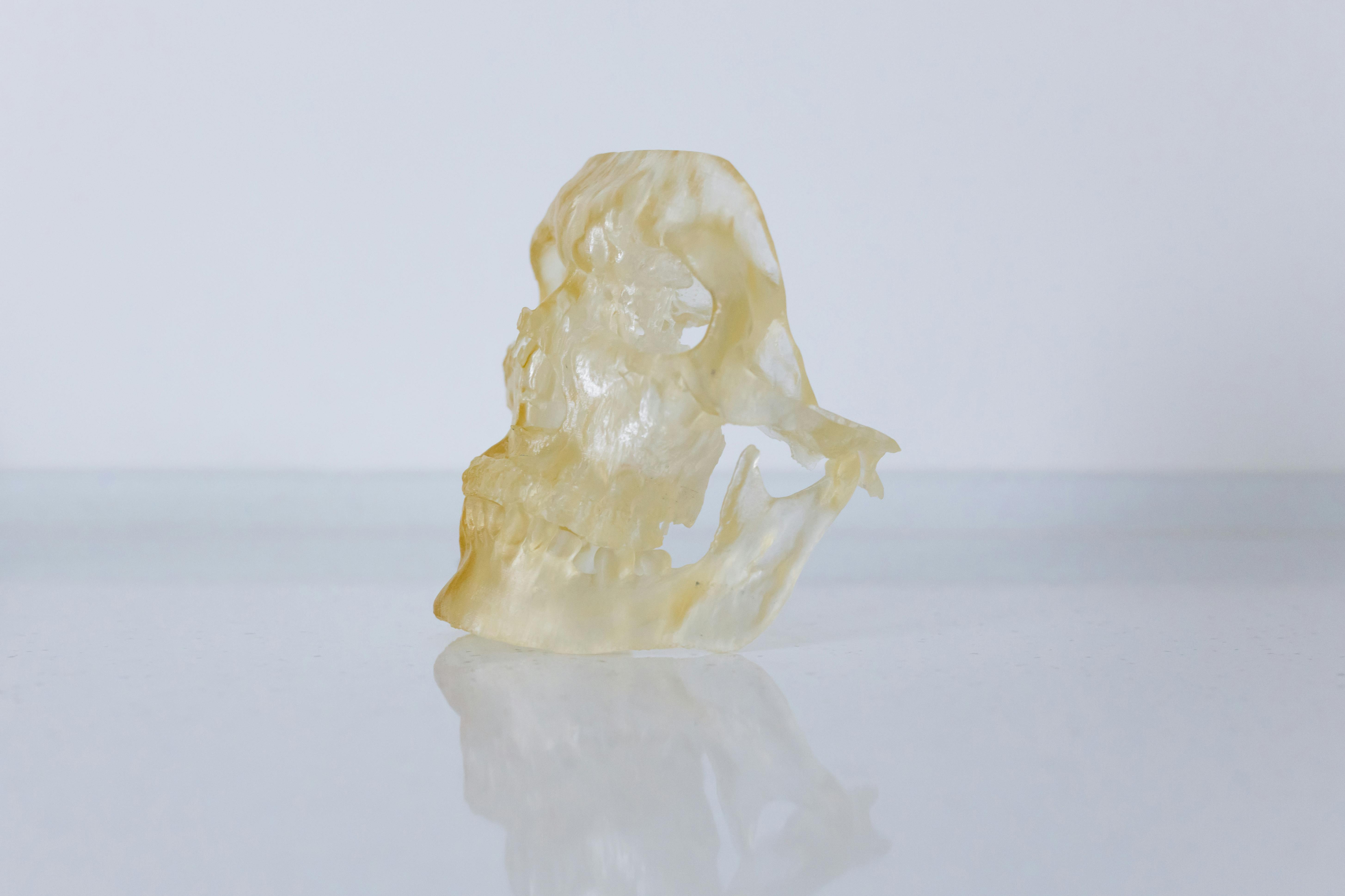
Every resin process starts from the same chemical principle: liquid photopolymers cure when exposed to light of a specific wavelength. The difference lies in how the light is delivered and how the part is supported during formation. SLA uses a UV laser to trace each layer; DLP uses a projector to expose an entire layer at once; Carbon's DLS continuously pulls parts from a resin vat through an oxygen-permeable window, curing them in real-time; PolyJet jets droplets of resin like an inkjet and cures them instantly, allowing multiple resins to be printed side-by-side in the same part. These four mechanisms lead to entirely different engineering outcomes, and calling them all "resin printing" obscures most of the truly critical decisions.
Quick Comparison of Four Resin Processes
| Process | Light Source Mechanism | Typical Layer Thickness | Batch Throughput | Material Breadth | Best For |
|---|---|---|---|---|---|
| SLA | UV laser traces each layer | 25–100 µm | Slow for dense layers, fast for sparse layers | Very broad—standard, engineering, clear, high-temp, castable | Fine details, clear parts, casting masters, precision hardware |
| DLP / MSLA | Projector exposes entire layer | 25–100 µm | Layer time independent of part count | Broader, adjusted by resin manufacturer | Small parts, high throughput (dental, jewelry) |
| DLS (Carbon) | Oxygen-permeable window + near-continuous projection | 20–100 µm | Fast for high part counts | Narrower but engineering-grade; EPU / RPU / EPX / MPU series | Mass-produced elastomers, engineering-grade resin parts |
| PolyJet | Multiple printheads jetting + instant UV | 16–27 µm | Medium, depending on part footprint | Unique—multiple resins in one build | Multi-material concepts, overmolding simulation, coexisting transparency and rigidity |
Layer Thickness: What the Numbers Really Mean
Layer thickness is the most prominent number on the spec sheet, but its useful translation is "what features can it resolve cleanly." 100 µm is sufficient for most functional prototypes and is three to four times faster than 25 µm; 25 µm is the threshold where < 1 mm raised text is readable and curved surfaces appear smooth to the naked eye; 16 µm (PolyJet) is the threshold for achieving "production-intent level surfaces" and where fine textures truly print as modeled in CAD. The trade-off is always time: halving the layer thickness roughly doubles the build time.
| Layer Thickness | Features that can be reliably resolved | When to choose |
|---|---|---|
| 100 µm | Walls ≥ 0.8 mm, text ≥ 2 mm, simple curved surfaces | Rapid functional prototypes, fitment checks, concept reviews |
| 50 µm | Walls ≥ 0.5 mm, text ≥ 1.2 mm, hinge-level details | General engineering prototypes |
| 25 µm | Walls ≥ 0.3 mm, text ≥ 0.8 mm, optical-grade smooth surfaces | Patient-specific devices, jewelry, small precision parts |
| 16–20 µm (PolyJet class) | Walls ≥ 0.2 mm, texture patterns, aesthetic surfaces | Production-intent aesthetic models, multi-material parts |
The Full Landscape of Resin Materials
The same machine can run over ten types of resins that behave like ten different materials. The names on the bottle (ABS-like, PP-like, rubber-like) are merely directional descriptions, not performance guarantees—printed parts rarely truly match the fatigue, impact, or long-term stability of the injection molded material they imitate. More useful than the name is comparing three technical numbers: HDT (Heat Deflection Temperature), Shore Hardness / Tensile Modulus, and Elongation at Break.
| Family | Tensile (MPa) | HDT (°C) | Elongation at Break | Hardness | Typical Applications |
|---|---|---|---|---|---|
| Standard | 50–65 | 55–65 | 5–8% | 80D | Concept models, visual review |
| Tough / ABS-like | 35–50 | 45–60 | 15–50% | 70–85D | Functional prototypes, tactile feel |
| Rigid Engineering | 65–80 | 75–120 | 3–6% | 85D+ | Rigid structures, jigs, fixtures |
| Clear (Standard) | 45–60 | 55–75 | 8–12% | Approx. 80D | Fluid demos, optical concepts |
| Clear High-Temp | 55–80 | 180–238 | 3–6% | Approx. 87D | Autoclave medical, glass-like feel |
| Castable | Tuned for burnout, low strength | Not applicable | Almost none | Wax-like | Jewelry, lost-wax casting masters |
| Flexible / Elastomeric | 4–12 | Not applicable | 80–250% | 40A–85A | Soft grips, gaskets, tactile studies |
| Ceramic-filled | 60–90 | 150–250 | < 3% | 95D | High HDT jigs, mold inserts |
| Biocompatible / Dental | Varies by grade | Varies by grade | Varies by grade | Varies by grade | Dental crowns, clear aligners, surgical guides |
Industrial-grade vs. Desktop Resin Printing
Desktop MSLA can genuinely achieve good results—at the same Shore hardness or layer thickness specifications, a well-tuned desktop machine can produce parts that look very similar to those from industrial-grade machines. The difference lies in repeatability and material breadth, which are precisely what matters for production or client-facing work.
| Item | Desktop MSLA | Industrial SLA / DLP / DLS / PolyJet |
|---|---|---|
| Month-to-month layer consistency | Drifts with LCD / UV aging | Maintained with calibration and QA |
| Build volume | ≤ Approx. 200 × 130 × 200 mm | Industrial SLA up to 400 × 400 × 500 mm |
| Material menu | Mainly standard + tough + some flexible | Full menu including high-temp, castable, ceramic, engineering-grade |
| Support algorithms | General slicers, manual fine-tuning | Supplier-tuned for resin and geometry |
| Batch-to-batch repeatability | Acceptable for proof of concept | Production-grade, documented |
| All-in cost per part (small batch) | Approx. $5–15 | Approx. $20–80 |
| When it wins | Internal iteration, low-risk concepts | Client-facing, critical dimensions, production intent |
Post-Processing is Part of the Build
Resin parts are not finished when they come off the machine. To be complete, they must undergo washing, post-curing, and (if applicable) support removal and surface finishing. Each step can affect dimensions, alter mechanical properties, and has its own failure modes.
| Step | Function | Typical Time | Dimensional Impact |
|---|---|---|---|
| IPA Wash (or supplier solvent) | Removes uncured resin from surface | 5–20 minutes | Green parts may temporarily swell 0.3–0.8% |
| Drain / Air Dry | Allows solvent to evaporate | 15–45 minutes | Shrinks back after solvent evaporation |
| UV Post-cure | Completes polymerization; achieves final strength | 10–60 minutes @ 40–80°C | Shrinks 0.2–0.8%, thin sheets may warp |
| DLS Thermal Post-cure | Second thermal post-cure for Carbon engineering resins | 2–8 hours @ 110–160°C | Negligible with supports, significant without |
| Support Removal | Manual or tool-based support removal | 5–30 minutes per part | Leaves marks if not sanded |
| Sanding / Polishing / Vapor Smoothing | Achieves Ra ≤ 1 µm when required | 15–90 minutes per part | Removes 0.05–0.2 mm per surface |
| Painting / Coating | Color, UV barrier, chemical resistance | Overnight | +0.05–0.15 mm per coat |
DFM Values for Resin Parts
Resin can resolve finer features than any other polymer additive manufacturing process, but there are still limits. The table below lists safe default values for industrial SLA, DLP, and DLS; PolyJet can achieve about 30% finer details but also requires more precise support removal. All values refer to the final part after post-curing, not the green part.
| Feature | Industrial SLA / DLP / DLS | PolyJet | Notes |
|---|---|---|---|
| Structural Wall | 0.5 mm | 0.3 mm | Thinner can print but will warp during post-cure |
| Supported Wall (Rib / Column) | 0.3 mm | 0.2 mm | Aspect ratio ≤ 10:1 |
| Raised Text | 0.4 mm width × 0.4 mm height | 0.2 mm × 0.3 mm | Sans-serif fonts survive better |
| Engraved Text | 0.4 mm width × 0.4 mm depth | 0.25 mm × 0.3 mm | Depth must be greater than layer thickness |
| Hole Diameter | 0.5 mm | 0.3 mm | Round holes are more stable than slotted holes |
| Clearance for Moving Parts | 0.2–0.4 mm | 0.15–0.3 mm | Varies by resin; verify with test parts |
| Unsupported Overhang Angle | ≥ 30° from horizontal | ≥ 25° | Supports mandatory below this angle |
| Drain Hole for Hollow Parts | Diameter ≥ 3 mm, two holes | ≥ 2 mm, two holes | Residual resin adds weight and warps during post-cure |
Application Cases
Autoclave-Resistant Clear Fluid Manifold
The endoscopic demo fluid manifold mentioned at the beginning—with a 1.2 mm internal channel, optical clarity for camera-based fluid tracking, and daily autoclave sterilization—ultimately used industrial SLA with a high-temperature clear resin (HDT 238°C). After washing, it was fully post-cured in a UV oven, then vapor smoothed to Ra ≤ 1 µm. Drain holes were placed at the bottom of the manifold to ensure no residual liquid resin. It passed 300 sterilization cycles without any new cracks; camera fluid tracking accuracy met the original specifications. Post-curing took three 40-minute sessions (each with different orientations) to ensure residual optical stress dissipated evenly.
Key design action: Specifying the HDT requirement (autoclave = 134°C) from the start allowed the supplier to select the material, rather than the team merely requesting "clear resin." This step transformed the design from "will crack after the second autoclave" to "passes 300 cycles."
Dental Orthodontic Models – Throughput Drives Process Choice
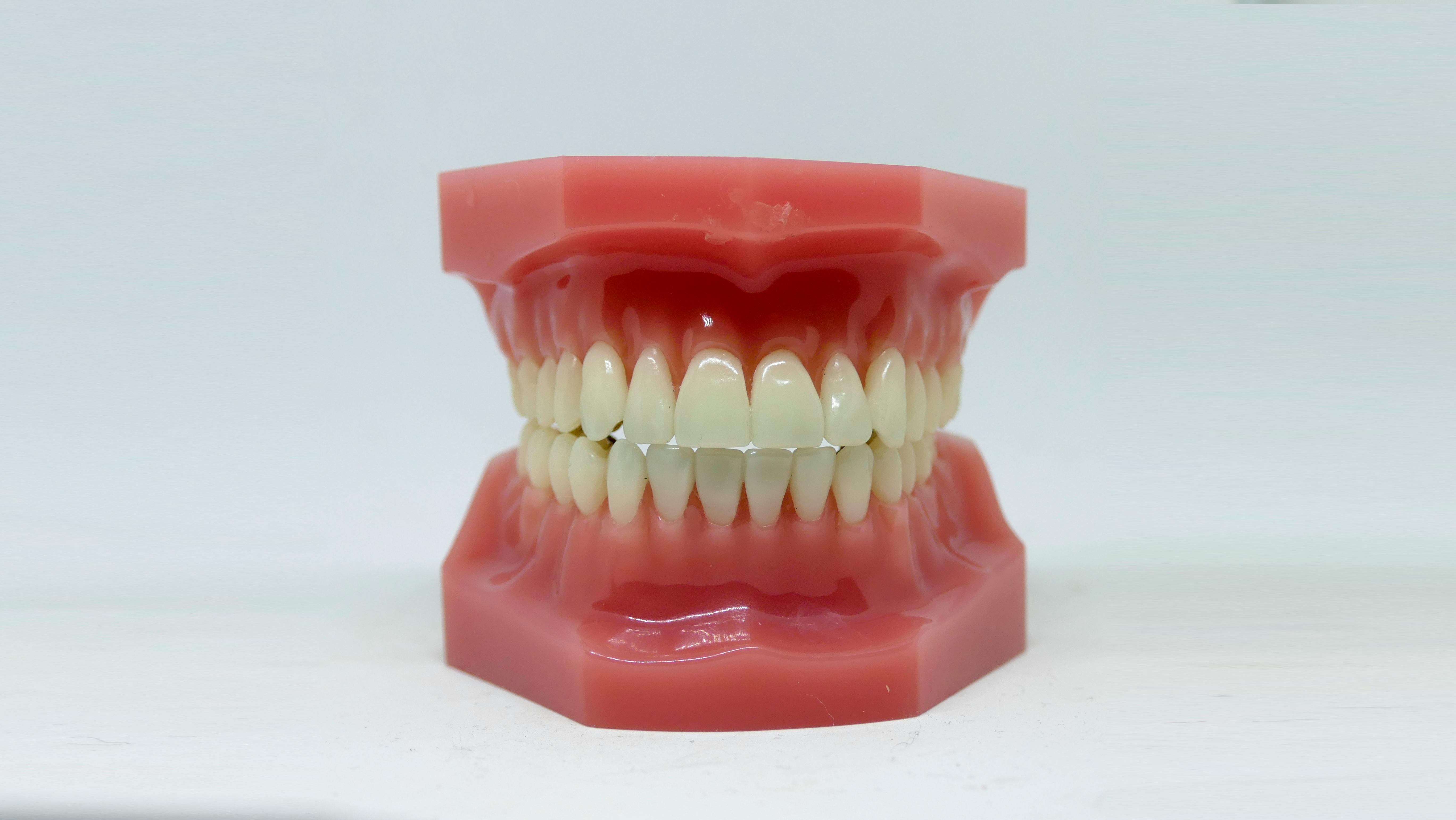
A medium-sized dental lab prints 200–400 orthodontic models daily. Early on, they used SLA because they already had the machines; a single build took six hours for 15 parts. Switching to a DLP-type machine for the same batch of 15 parts reduced the build time from six hours to 55 minutes—because DLP's projector exposes the entire layer at once, regardless of how many parts are on the build platform; layer time is fixed, filling the platform is free. The per-part resin cost increased slightly (DLP-tuned resins are more expensive), but throughput tripled, allowing the dental lab to eliminate a night shift. This wasn't a "which is more accurate" question (both easily met dental tolerances)—but "which process's time mechanism aligns with the actual volume of this dental lab."
PolyJet Multi-Material Concepts Justify Their Price
A consumer electronics brand needed a concept part before tooling: a rigid PC-like body, a soft TPU-like grip, and a clear light pipe—the production intent was three-material overmolding. Cutting and bonding each material was possible but slow (monthly reviews were spent assembling sticky parts), making the parts feel like assemblies rather than products to reviewers. PolyJet printed three materials at once: a rigid shell, a 60A grip, and a clear light pipe, with material interfaces directly printed, not bonded. The cost per part was about 4 times that of an equivalent SLA part, but the reviewers' decision iteration rate went from "one major change per round" to "one minor change per round"—because the prototype's behavior finally approximated the production overmolded part. A crucial caveat was explicitly stated throughout: PolyJet multi-material simulates overmolding behavior, but it's not equivalent to overmolding—any decisions dependent on interface strength were deferred until injection molded samples were available.
Do's and Don'ts
| Do | Don't |
|---|---|
| Select process and resin family together, aligning with primary requirements | Only specify "resin" without defining family and HDT / Shore targets |
| Use marketing names (ABS-like) as a guide, then verify | Assume ABS-like printed parts are equivalent to injection molded ABS in fatigue or impact |
| Include cleaning, post-curing, and post-processing in dimensional annotations | Measure dimensions immediately after washing |
| Choose layer thickness based on "what needs to be resolved" | Default to the smallest layer thickness for every part |
| Use PolyJet when multi-material is a true requirement | Choose PolyJet for single-material production parts |
| Prioritize industrial-grade for client-facing or dimension-critical work | Assign month-to-month repetitive tasks to desktop machines |
| Allow a safe margin for HDT window | Put standard HDT resin into autoclaves or sustained high temperatures |
Common Mistakes and How to Avoid Them
| Mistake | Why it Fails | How to Avoid |
|---|---|---|
| Dimensional inspection in green state | Resin not fully polymerized; dimensions still shifting | Inspection points set after full post-curing |
| Resin trapped in hollow parts | Uncured resin adds weight, leaks, and warps during post-curing | Any enclosed volume must have at least two ≥ 3 mm drainage holes |
| Standard HDT clear resin exposed to high-pressure steam | 134°C cycle is about 70°C higher than HDT; cracking after 1–3 cycles | Always specify high-temperature clear resin for sterilization scenarios |
| Painting aesthetic surfaces before post-curing | Solvents attack green resin; paint delaminates afterward | Paint only after full post-curing |
| Using desktop printers for client-facing dimensional work | Inter-batch layer thickness drift compromises repeatability | Use industrial platforms with calibration documentation |
| Treating PolyJet multi-material as production equivalent | Behavior of jetted multi-resin interfaces differs from overmolding | PolyJet for concepts only; validate interface-related decisions with injection molded samples |
Pre-Submission Validation Checklist
Run through this list before uploading your CAD. Each item helps guide the build in the right direction or prevents a category of failures that only appear after post-curing.
- The drawing specifies resin family, Shore/HDT targets, and primary use environment.
- Process (SLA / DLP / DLS / PolyJet) selected based on primary requirements, not available equipment.
- Layer thickness determined by the smallest feature requiring clean resolution.
- All enclosed hollow volumes have at least two ≥ 3 mm drainage holes.
- Overhangs below 30° have been supported; support marks do not fall on aesthetic or mating surfaces.
- Post-processing level for each surface is noted, and dimensional impact of each step is considered.
- Inspection points are set after full post-curing, not after cleaning.
- Client-facing or dimension-critical work confirmed to use industrial platforms with calibration records.
Design Key Takeaways
Resin printing is not one process, but four; each excels where the others falter. SLA for details, DLP for throughput, DLS for engineering-grade production, and PolyJet for multi-materials. The resin used in the process is as important as the process itself—a clear resin with incorrect HDT, even if printed on an industrial SLA, will still crack after high-pressure steam. Treating the "process + resin family + post-processing chain" as an integrated decision, rather than three separate procurement fields, is the most effective way to ensure successful resin part delivery on the first try.


0 comments