
A medical device grip, printed with flexible photopolymer resin, passed every static compression test on the workbench, fitted cleanly into its housing, and received a thumbs-up for feel from clinicians. Three weeks later, in field tests, the grip cracked at its base under repeated twisting. The problem wasn't strength; it was fatigue—something static tests wouldn't reveal. Flexible 3D printing is one of those design areas where you feel like you've "solved it" during a demo, only to realize the real challenge begins at mass production.
When to Adopt Flexible 3D Printing
Flexible additive manufacturing offers clear value when the design problem isn't about form but controlled compliant behavior, and when volume or customization makes traditional molding uneconomical. The sweet spot is the intersection of "low-to-medium volume, geometric customization, and cyclical motion requirements."
| Scenario | Why Flexible Additive is a Fit | Expected Cycles / Volume |
|---|---|---|
| Soft-touch grips for low-volume consumer products | Colors and geometries vary across different SKUs | 10k–100k cycles, 100–2,000 units/SKU |
| Custom prosthetic or orthotic sockets | Each geometry is patient-specific | Daily use, 1 unit per patient |
| Compressible seals on pre-production hardware | Design freeze validation before molding | Hundreds of compression cycles for validation |
| Vibration dampening mounts for prototype robotics | Design iterates weekly | 10k–1M cycles after validation |
| In-situ printed living hinges on consumer devices | Injection molding requires two-shot molding | 100,000+ open/close cycles |
Process Options for Flexible Parts
Four additive manufacturing routes can produce bendable parts, but their durability varies significantly. Flexible SLA resins offer good detail and speed but have low cyclical durability. Silicone-feel photopolymers can provide true skin-like tactile feel, but batch sizes are small and costs are high. MJF and SLS TPU are the default answer for most mid-volume flexible parts. Carbon DLS EPU excels in extremely high cyclical requirements but costs about twice as much as MJF. FDM TPU filament is the cheapest but has low dimensional accuracy and weak layer adhesion—it's reasonable for exploratory prototypes but think twice before shipping to customers.
| Process + Material | Shore Hardness Range | Elongation at Break | Typical Cycle Life | Relative Cost | Best Suited For |
|---|---|---|---|---|---|
| SLA Flexible Resins | 50A–85A | 50–120% | 1k–50k cycles | 1.0× | Appearance/fit prototypes, haptic studies |
| SLA Silicone-Feel Resins | 40A–70A | 250–400% | 5k–50k cycles | Approx. 1.5× | Realistic haptics, soft seals (prototyping) |
| SLS / MJF TPU | Approx. 88A–95A | 100–250% | 100k–1M+ cycles | Approx. 1.3× | Production flexible parts, lattice cushioning, living hinges |
| Carbon DLS EPU | Typically 70A–80A | 200–300% | 100k–1M+ cycles | Approx. 1.8× | High-fidelity production elastomers, medium-cycle seals |
| FDM TPU Filament | 85A–95A | 300–500% | 10k–500k cycles | Approx. 0.8× | Low-volume functional parts, simple geometries |

Read Shore Hardness Correctly, Don't Guess
Shore hardness is the most useful single number on a flexible material datasheet, and it's also the most frequently skipped during design reviews. Shore A covers soft elastomers (rubber bands, tire treads, shoe soles); Shore D begins with rigid plastics. Every 10-point jump on the scale results in a noticeable difference in feel—no one would confuse the feel of a 70A gasket with an 85A gasket. The table below maps the scale to everyday reference objects, turning "around 80A" into a decision, not a guess.
| Shore Level | Everyday Reference Object | Typical Use for Flexible Parts |
|---|---|---|
| 20A | Gel insoles, stress balls | Impact absorption, high-compliance seals |
| 40A | Rubber bands, erasers | Soft-touch overmolding, skin-contact cushioning |
| 60A | Car tire treads, door seals | Gaskets, vibration dampeners |
| 80A | Skateboard wheels, shoe heels | Production flexible parts, living hinges, bumper blocks |
| 95A | Shopping cart wheels, hard grips | Structural flexibility, abrasion-resistant bushings |
| 55D | Helmet shells, golf ball cores | Semi-rigid structures with slight compliance |
Material Selection Framework
A useful shortcut: don't pick the material first. Instead, write down the three numbers the material absolutely must hit. Target hardness (a 10-point Shore range), minimum rebound after 24 hours of peak compression (typically 75–90% for most TPU grades), and target cycles at the actual strain amplitude. Once these three are defined, most options will disappear, leaving one or two to filter based on the operating environment. Flexible parts most often degrade in chemical environments: IPA wipes (common in medical and semiconductor cleanrooms) can cause TPU to swell 2–5% and reduce hardness by 5–10 Shore; long-term UV exposure can reduce rebound within months; temperature—above 60°C—accelerates all of these effects.
| Operating Environment | Effect on TPU / Elastomers | Design Action |
|---|---|---|
| IPA / Ethanol (medical wipes) | Swelling 2–5%; hardness decrease 5–10 Shore A | Select IPA-compatible grade; re-validate force window after wiping |
| High Temperature > 60°C | Accelerated permanent deformation, reduced rebound | Design for operating temperature 50% below datasheet limit |
| UV / Outdoor Exposure | Brittleness, discoloration within months | Select UV-stabilized grade or enclose in opaque housing |
| Oils and Hydrocarbons | Swelling, softening, potential leaching | Switch to higher hardness TPU or fluoroelastomer |
| Repeated Sterilization (autoclave) | Hydrolysis, reduced rebound | Replace standard TPU with silicone-feel or PEBA |
| Low Temperature / Freezing | Hardening, impact embrittlement | Ensure glass transition temperature is below lower operating limit |
Geometric Rules for Extending Life
The key to durable flexibility is controlled strain distribution. If a thickness change from 2 mm to 4 mm has no transition, the strain concentration at the boundary is typically 3–5 times the nominal bending strain; cracks will start there on the 100th or 1000th cycle. Truly effective design actions are simple—just some radii and tapers that "didn't break during the demo so engineers repeatedly ignore them."
| Feature | Recommended Geometry | Why It's Important |
|---|---|---|
| Thickness Transition (Rigid ↔ Flexible) | Taper length ≥ 3 × thickness difference | Avoid 3–5x strain peak at steps |
| Fillet at Bending Root | ≥ 1.5 × local thickness | Sharp corners are fatigue initiation points; fillets distribute strain |
| Minimum Flexing Cross-Section | TPU powder bed ≥ 1.5 mm; FDM TPU ≥ 1.0 mm | Too thin amplifies strain amplitude for the same deflection |
| Hole / Embossed Text Placement | Distance from bending path ≥ 3 × hole diameter | |
| Flexing Length vs. Deflection | Flexing length ≥ 8 × deflection distance | Keeps bending strain below 5% (common fatigue safe zone) |
| Isolated Fixed Islands | Keep fixed features on rigid islands; add relief grooves between island and flexible zone | Avoid assembly pre-load adding to fatigue path |
Tolerance Strategy for Flexible Interfaces
If you dimension flexible parts like rigid machined parts, you're doing it wrong. The linear dimensions of a snap-fit aren't measured on the assembly line—they feel the insertion force. The linear dimensions of a seal aren't what's sealing—it's the compression ratio. The practical approach is to first define the functional goals (force window, compression ratio, seal contact pressure), then let geometry be the means to achieve those goals, and explicitly allow for the post-processing chain it will undergo.
| Interface Type | Prioritized Definition | Typical Target | Then Back-Calculate |
|---|---|---|---|
| Snap Fit | Insertion / Removal Force Window | Consumer scale 10–25 N insertion, 15–35 N removal | Cantilever thickness, latch length, leading edge chamfer |
| Compression Seal | Compression Ratio | Static 15–30%, Dynamic 8–15% | Nominal thickness vs. groove depth |
| Dynamic Gasket | Seal Contact Pressure | Elastomeric seals 0.5–1.5 MPa | Cross-section geometry, groove gap |
| Soft Press-Fit Grip | Interference Percentage | 80A TPU radial interference 3–7% | Hole diameter vs. grip outer diameter |
| Living Hinge | Bending Angle × Number of Cycles | 90° ± 5° over 100k cycles | Hinge thickness, root radius |
Orientation and Anisotropy
Every layered process has weaker layer interfaces. In flexible parts, this asymmetry is not a minor issue—it's the difference between a "hinge lasting 100,000 cycles" and a "hinge delaminating after 2,000 cycles." The safety rule is: orient the part so that the main bending strain is across layers, not along them. If a living hinge's fold line is parallel to the layer planes, each cycle will open the layer interfaces, leading to early failure; rotating the same hinge by 90° so the fold line is across layers typically increases lifespan by one to two orders of magnitude.
An extended conclusion: the orientation of flexible parts is a "production freeze" decision, not a batch-by-batch optimization. Once the validated orientation for cyclical performance is confirmed, use that same orientation for every subsequent batch—even if auto-nesting software tries to flip it.
Application Cases
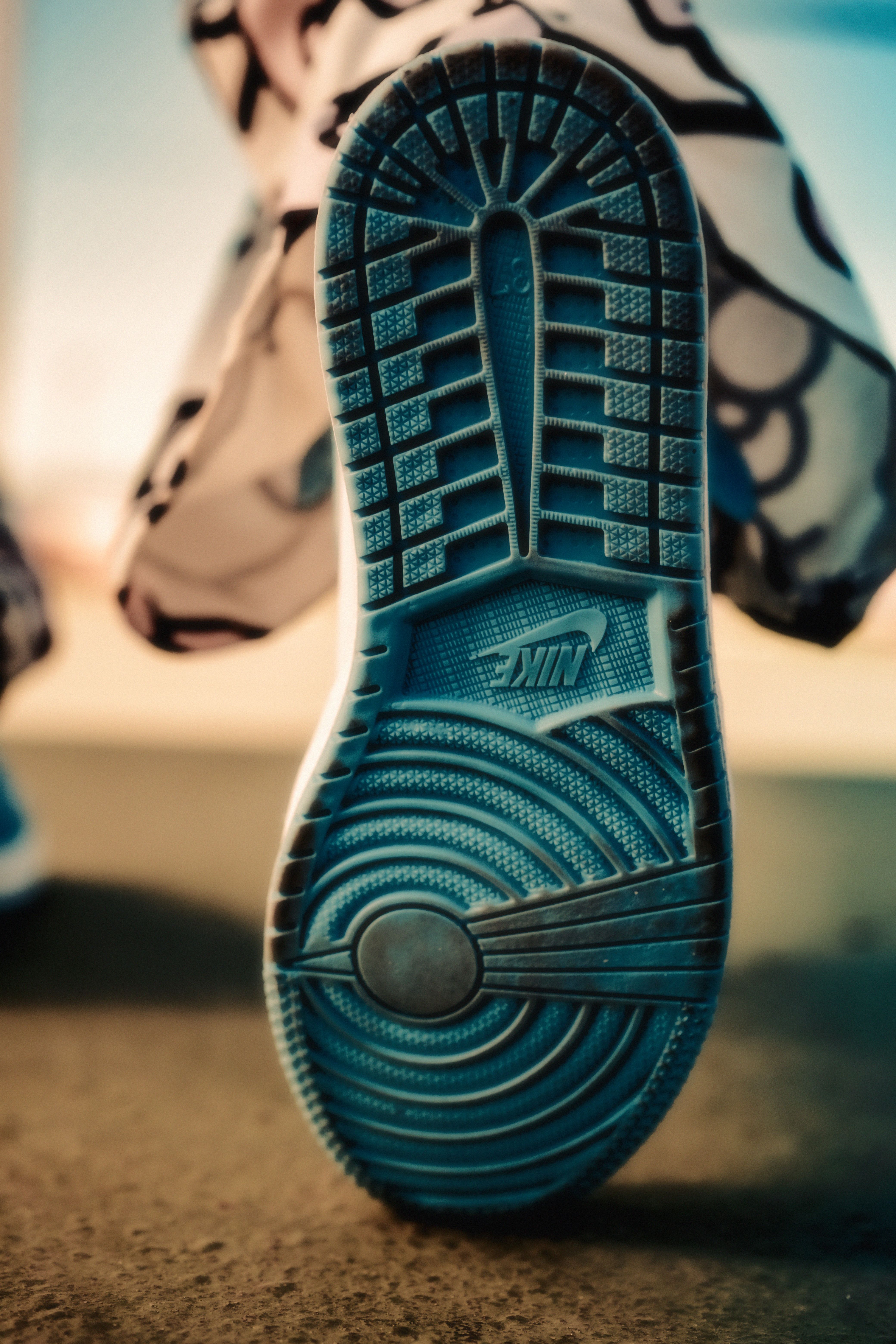
Custom Lattice Midsole for a Running Shoe Brand
A running shoe brand offers custom midsoles as a premium option, created by gait scanning. The base material is MJF TPU Shore 90A, printed as a gradient lattice—softer in the forefoot (effective modulus approx. 0.3 MPa) and firmer in the heel (approx. 0.8 MPa). Monthly volume is about 1,200 pairs, spanning 60 size/gait combinations—too many SKUs for injection molding, and individual SKU volumes too low to justify steel tooling. The critical durability metric isn't tensile strength, but compression set after 500,000 cycles at 30% strain. The lattice geometry was iterated three times to reduce this figure to below 8%.
Key design actions: The stiffness transition from forefoot to heel was tapered over 40 mm, not stepped. Early versions with a rigid step cracked at the transition around 40,000 cycles—precisely where runners land midfoot. Changing to a taper pushed the first crack to over 400,000 cycles, transforming the part from a "nice demo" to a "shippable SKU." Orientation locked: Lattice build direction aligned with the compression axis, no new orientations without cyclical validation allowed for production release.
IPA-Resistant Prosthetic Socket Liner
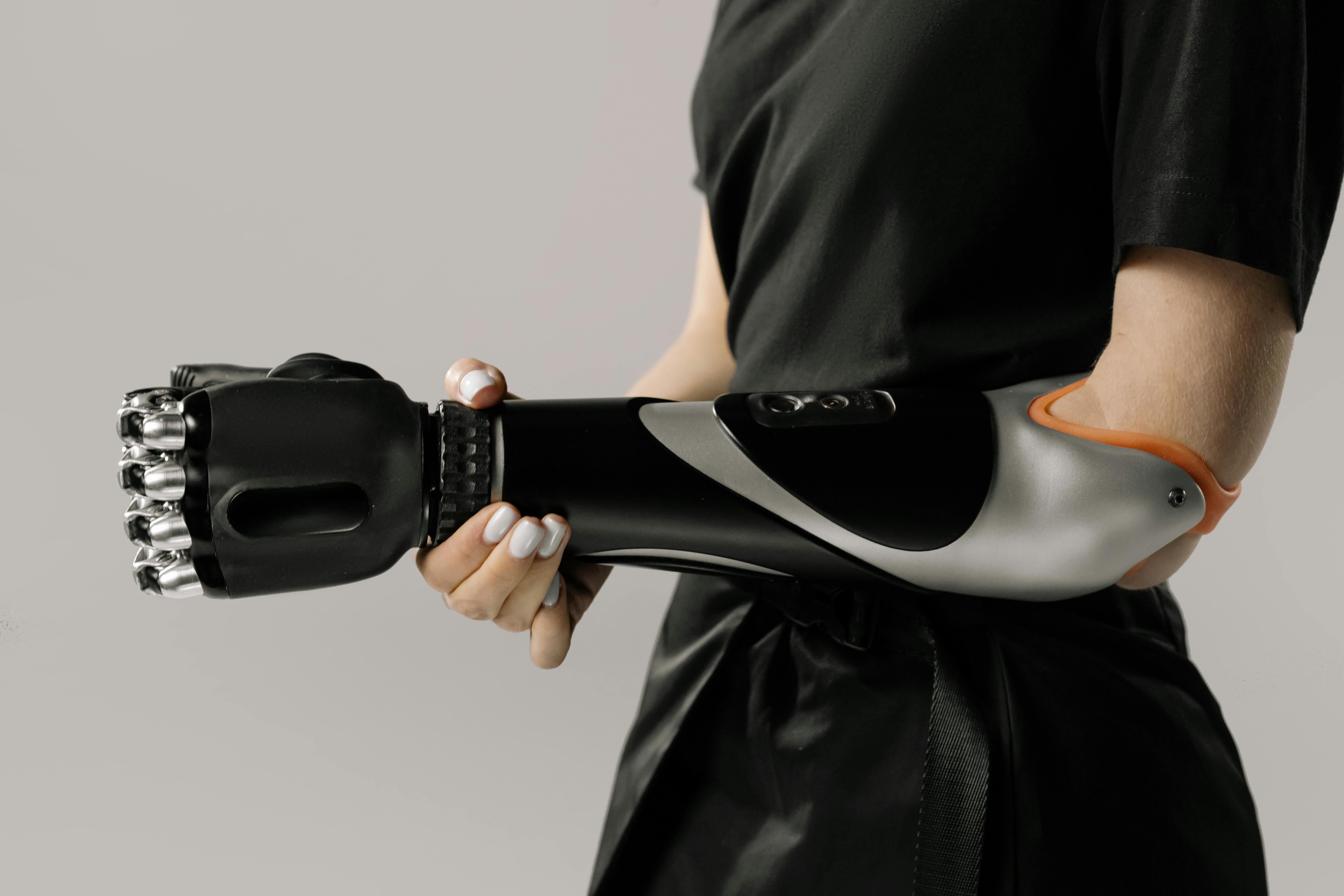
A clinical unit 3D prints upper limb prosthetic socket liners based on patient scans. Early versions used standard Shore 70A TPU, which felt good on first wear—but within two weeks, daily IPA wiping reduced hardness by 5 Shore. The material was switched to an IPA-resistant TPU grade (slightly more expensive, slightly harder at 80A), and internal geometry was thickened by 0.3 mm to compensate for the higher hardness. The second-generation liner showed hardness fluctuations of ≤ 2 Shore over a six-month wear cycle and has become the default option for patients following standard hygiene protocols at that clinic. The key wasn't an abstract "better material"—but matching the material to the actual chemical cleaning conditions used daily by that patient population.
Living Hinge Cover with >95% First-Pass Assembly Yield
A consumer device required a flip cover that would be opened and closed thousands of times during use. Early prototypes used SLA flexible resin—judges found the feel acceptable, but every test piece cracked between 800 and 2,000 cycles. The production version switched to SLS TPU 92A, with a hinge thickness of 1.3 mm, a 2 mm root radius, and the fold line oriented across layers. Critical tolerances were defined by a force window of 8–12 N, not linear dimensions. The assembly line achieved over 95% first-pass yield, and QA labs confirmed the hinge survived over 150,000 open/close cycles—about 30 times the SLA version, and well beyond the product warranty usage profile.
Common Failure Modes and Design Countermeasures
| Failure Mode | Initiation Location | Design Countermeasure |
|---|---|---|
| Early crack at thickness step | Boundary from rigid to flexible | Taper transition ≥ 3 × thickness difference; min root radius 1.5 × thickness |
| Permanent deformation altering fit | High strain compression zone | Set static strain below 30%; specify minimum rebound; switch to high-rebound grade if needed |
| Rigid-flexible delamination | Bonding or transition interface | Switch to mechanical interlocking geometry; don't rely on adhesion alone for stress seams |
| Fold line layer separation | Fold line parallel to layer plane | Rotate fold line to be across layers; freeze build orientation for production |
| Assembly force outside window | No functional tolerance defined | Tolerance by force, not linear dimensions; re-validate after post-processing |
| Chemical softening during use | Surface exposed to cleaning agents / oils | Screen for compatibility with actual use chemicals before release |
Do / Don't Comparison
| Do | Don't |
|---|---|
| Define cycle profile before selecting material | Select based solely on Shore hardness |
| Tolerance interfaces by force or compression ratio | Use tight linear tolerances for flexible parts |
| Design fold lines to be across layers and freeze orientation | Allow auto-nesting to re-orient between batches |
| Screen for IPA, oil, UV, temperature compatibility before release | Assume datasheet numbers directly apply to real-world use |
| Taper thickness transitions with ≥ 3× thickness difference | Directly step from 2 mm to 4 mm |
| Perform real-world cycle testing, not just static fit checks | Release based on a single successful first assembly |
| Transfer precision to rigid islands for tight tolerances | Expect flexible materials to achieve ±0.05 mm linear accuracy |
Pre-Release Validation Checklist
Run this checklist once during design review and again before first production release. Each item corresponds to a failure mode discussed above.
- Target Shore window, minimum rebound, and cycle targets are specified on the drawing
- Material has been screened for compatibility with actual cleaning agents / fluids / temperature conditions
- Every thickness transition is tapered with ≥ 3× thickness difference; every bending root has a minimum radius of 1.5 × thickness
- Functional tolerances (force, compression ratio, contact pressure) are specified, not just linear dimensions
- Build orientation is fixed and documented; fold lines are across layers
- Cyclical validation is performed at actual bending angles, rates, and temperatures—not convenient lab conditions
- Fit validation uses actual mating hardware intended for production, not simplified fixtures
- Rigidity and force have been re-measured after final post-processing
Key Design Takeaways
To succeed with flexible 3D printing, motion must be treated as a primary requirement. Select the process based on cycle targets and strain patterns, not just Shore hardness. Define functional goals (force window, compression ratio, rebound) first, then design geometry as the means to achieve those goals. Lock down the build orientation and validate under real-world chemical conditions—not demo conditions. By doing these things, flexible additive parts can transition from "interesting prototypes for show" to "shippable production components."


0 comments