
A drone startup sent a PA12 quadcopter arm: 142 mm long, 3.2 mm wall thickness, flown for 40 cycles at 6,500 RPM. After two months on a coastal rooftop, the arm fractured at the root of the mounting lug, even though the peak forces were far below the strength of dry samples. Root cause: PA12 absorbed ambient moisture, reducing its modulus by 25%, while the sharp internal corner at the lug's root created a 3× stress concentration point—these two factors combined to allow a crack to silently propagate.
This case highlights the real challenges of designing with nylon. Nylon is not a single material but a family; its properties change with humidity, manufacturing process, and powder lifespan; and geometric rules depend on the specific grade you choose.

The Nylon Family You'll Actually Choose From
Currently, in commercial additive manufacturing of nylon, 95% of cases fall into these five variants: PA12 (mainstay), PA11 (tough, bio-based), PA12-GF (glass fiber reinforced for stiffness), PA12-CF (short carbon fiber, highest specific stiffness), and mineral-filled PA12 (damping and dielectric applications). Other grades, including PA6 and PA66 powders, occasionally appear in special industrial scenarios, but the DFM rules do not differ significantly.
The table below should be viewed as a design space for trade-offs rather than a ranking. PA11 is not "better" than PA12, but more suitable when impact and fatigue resistance are required; PA12-CF is not "stronger" than PA12-GF, but it is the choice when the highest stiffness is needed and the budget allows.
| Grade | Tensile Strength (MPa) | Modulus (GPa) | HDT @0.45 MPa (°C) | Elongation (%) | Relative Cost |
|---|---|---|---|---|---|
| PA12 (SLS/MJF) | 48 | 1.7 | 170 | 20 | 1.0x |
| PA11 | 52 | 1.5 | 180 | 45 | 1.4x |
| PA12-GF (30%) | 52 | 3.2 | 175 | 9 | 1.3x |
| PA12-CF (10-15%) | 75 | 5.5 | 180 | 5 | 2.1x |
| PA12 Mineral-filled | 45 | 2.6 | 165 | 6 | 1.2x |
Processes: SLS, MJF, and FDM Nylon
The same PA12 chemical formulation behaves entirely differently under Selective Laser Sintering (SLS), HP Multi Jet Fusion (MJF), or Fused Deposition Modeling (FDM). Differences in density, isotropy, and surface quality are sufficient to alter your design strategy.
| Process | Density | Surface Ra (um) | Isotropy | Unit Cost | Batch Sweet Spot |
|---|---|---|---|---|---|
| SLS PA12 | ~95% | 8-12 | Good | Medium | 50-500 |
| MJF PA12 | ~99% | 6-10 | Very Good | Low to Medium | 100-2000 |
| FDM Nylon | 85-95% | 15-25 | Poor (Weak in Z) | Low | 1-50 |
Specific DFM Data for Nylon Powder Bed Processes
The following are the operational limits we use when quoting for MJF and SLS PA12. Please consider them as design minimums; load paths and precision-sensitive features should be thicker.
| Feature | PA12 | PA11 | PA12-GF | Remarks |
|---|---|---|---|---|
| Minimum Wall Thickness | 1.0 mm | 1.0 mm | 1.2 mm | 0.7 mm unsupported walls are risky |
| Minimum Hole Diameter | 1.5 mm | 1.5 mm | 2.0 mm | Smaller sizes easily trap powder |
| Assembly Clearance | 0.4 mm | 0.4 mm | 0.5 mm | Per mating surface |
| Live Hinge | 0.6 mm | 0.5 mm | N/A | PA11 can double cycle life |
| Snap Fit Beam | 1.0 mm | 1.0 mm | 1.5 mm | GF is more brittle and needs to be thicker |
| Powder Removal Hole (Enclosed Cavity) | 4 mm | 4 mm | 4 mm | One hole per ~100 cc of cavity |
| Minimum Raised Text | 0.8 mm width | 0.8 mm width | 1.0 mm width | Minimum depth 0.5 mm |
Humidity: The Hidden Variable Behind Every Nylon Part
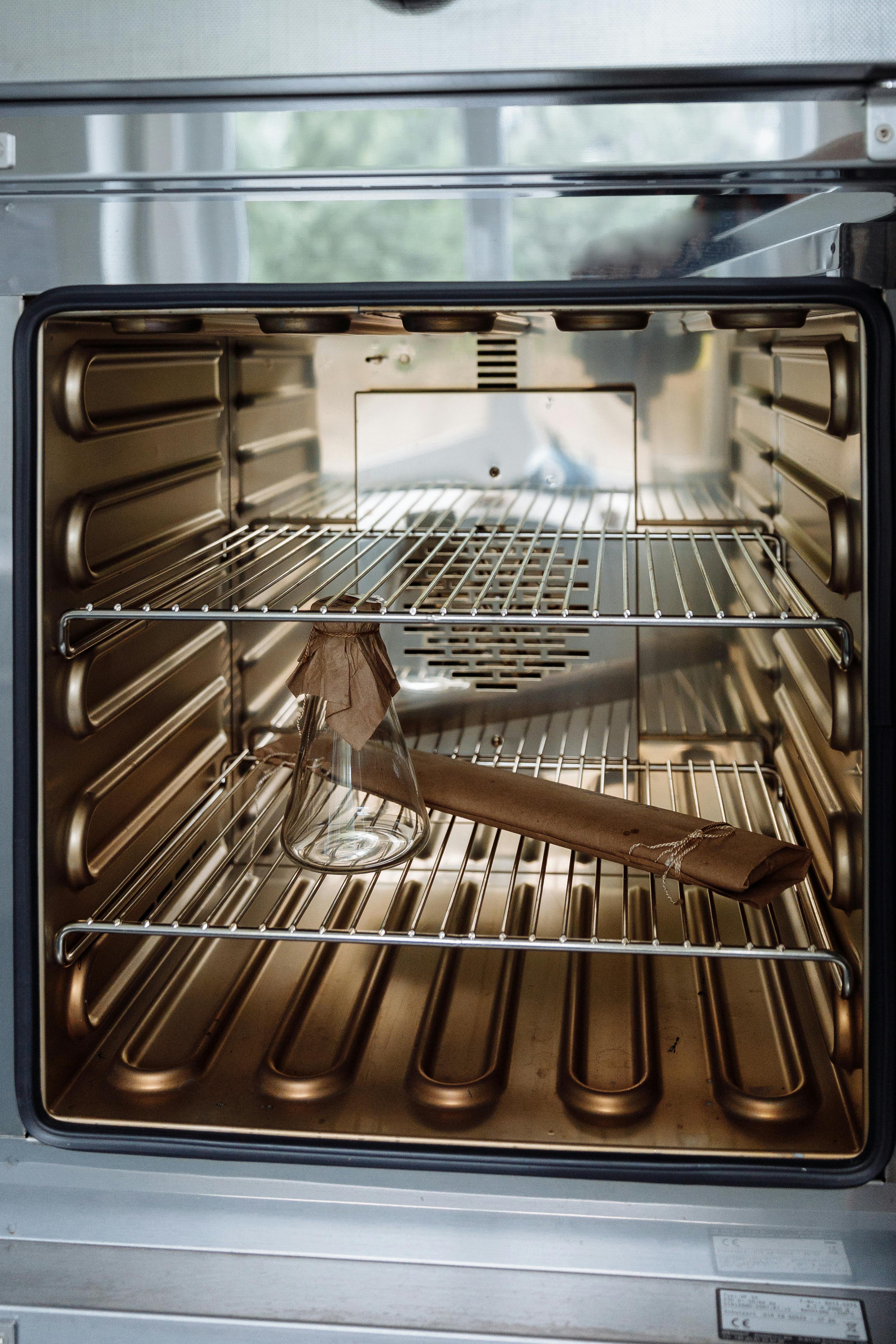
Nylon is hygroscopic. A dry, freshly printed PA12 part has about 0.3% water content, which stabilizes at 1.2-1.8% in a 50% RH office environment. During this change, the tensile modulus can decrease by up to 25%, while the overall part dimension increases by approximately 0.3%. For tight-tolerance fits, this cannot be ignored.
| Condition | Water Content | Modulus Change | Elongation | Dimensional Change |
|---|---|---|---|---|
| Dry from printer | 0.3% | Baseline | Baseline | Baseline |
| During transport (25% RH, 1 week) | 0.8% | -10% | +20% | +0.1% |
| Equilibrium (50% RH) | 1.5% | -25% | +50% | +0.3% |
| High humidity (80% RH) | 2.5% | -35% | +80% | +0.4% |
| Submerged (Saturated) | 3.5% | -40% | +100% | +0.5% |
Post-Processing: Surface Options for Nylon
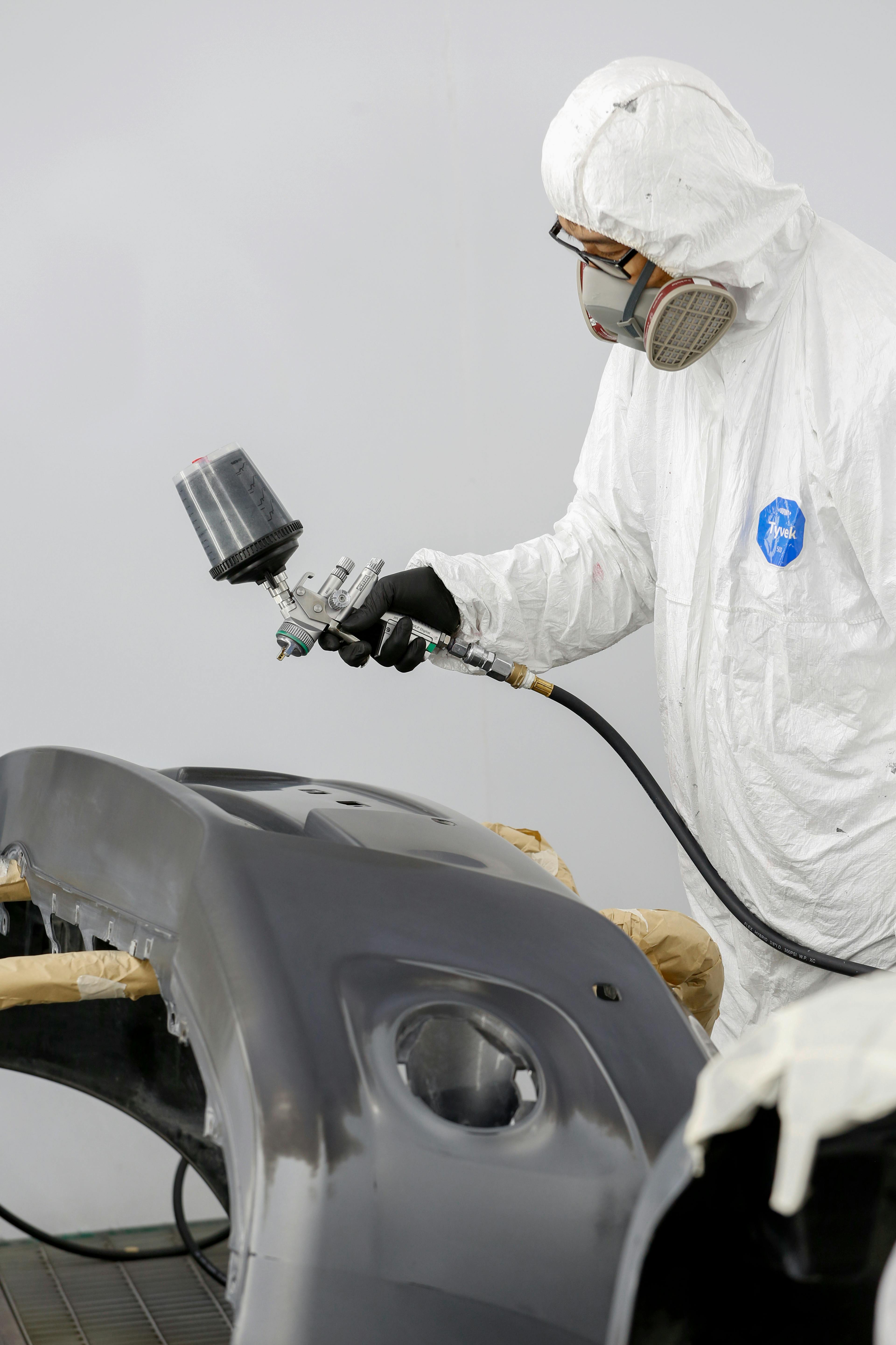
Always choose post-processing with a purpose: grip, aesthetics, sealing, or dimensional adjustment. Each step adds or removes thickness and alters surface chemistry, and DFM must account for these before finalizing the design.
| Post-Process | Thickness Change | Post Ra (um) | Typical Use | Cost Increase |
|---|---|---|---|---|
| Bead Blasting | -0.02 mm | 6-8 | Default matte finish | +5% |
| Vibratory Tumble | -0.05 mm | 3-5 | Consumer product feel | +10% |
| Vapor Smoothing | +0.08 mm | 1-2 | Sealing/Waterproofing | +25% |
| Dyeing (Black) | +0 mm | Same as original | Appearance | +8% |
| Primer + Paint | +0.1-0.2 mm | 1-3 | Specific color | +30% |
Applications: Three Nylon Case Studies
Case One: PA12-GF Drone Motor Mount, 30% Weight Reduction
A drone OEM for inspection needed a motor mount that was stiffer than PA12 and lighter than the existing 6061-T6 aluminum part (28 g). We redesigned it using PA12-GF 30%: 142 mm arm, 2.2 mm wall thickness with internal ribbing, all internal corners filleted to 0.8 mm, and two 5 mm powder removal holes for MJF powder egress.
Results after 300 flight cycles: Mount weighed 19.6 g (-30%), resonant peaks pushed above propeller frequency, zero cracks at rib junctions. Batch of 200 units at USD 18.40 each. The key to success was aligning modulus with the load path, rather than pursuing the strongest nylon.
Key design actions: Added 0.8 mm fillets to every internal corner; replaced solid cross-section with 2.2 mm walls + triangular ribbing; included 2 x 5 mm powder removal holes; oriented print direction so main stress was parallel to XY; dyed black for uniform appearance and UV protection.
Case Two: PA11 Medical Device Hinge, 100,000 Cycles Without Cracking
A handheld diagnostic device enclosure required an integrated live hinge, specified for 100,000 open/close cycles over 5 years. PA12 failed at 18,000 cycles; switching to PA11 with a hinge thickness of 0.5 mm, length 3 mm, and stress-relief fillets passed 110,000 cycles in accelerated testing.
Case Three: Enclosed Casing Trapping 42 g of Powder
A sensor housing without powder removal holes had 42 g of unfused powder rattling inside after MJF printing. By adding two 4 mm holes with 1 mm internal chamfers on a non-cosmetic surface, the powder was successfully removed, reducing powder removal time by 8 minutes per part. Lesson: Always model powder egress paths, not just the geometry.
Do's / Don'ts for Nylon Parts
| Do | Don't |
|---|---|
| Min wall thickness 1.0-1.2 mm and add ribs | Leave large unsupported flat areas |
| Add 4 mm powder removal holes for enclosed cavities | Trap powder in enclosed volumes |
| Add fillets to every internal corner (≥0.8 mm) | Leave sharp internal corners under load |
| Condition parts to end-use humidity before measuring | Set tolerances based on dry-from-printer dimensions |
| Choose PA11 for flexible/fatigue-resistant parts | Force PA12 to perform beyond 20,000 hinge cycles |
| Choose PA12-GF for stiffness, PA12-CF for specific stiffness | Treat GF and CF as interchangeable |
| Dye black first for aesthetic requirements | Machining after dyeing exposes white interior |
Common Errors in Nylon Design Review
| Error | Symptom | Correction |
|---|---|---|
| No powder removal holes | Rattling powder, hidden weight | Two 4 mm holes per 100 cc cavity |
| Sharp internal corners | Cracking at rib roots | 0.8 mm fillets on all internal corners |
| Tight fits with dry parts | Jamming after 2 weeks in office environment | Allowance of +0.3% or precondition parts |
| Applying PA12 DFM to PA12-GF | Brittle snap fits | Thicken beams to 1.5 mm |
| No tolerance for vapor smoothing | Too tight press fit | Add 0.08 mm to each smoothed surface |
| Dyeing after machining | Exposing white interior | Machine first, then dye |
Pre-Print Checklist
Run this checklist before releasing every nylon part. It takes only five minutes but can catch errors that would require a reprint.
- Selected grade (PA12 / PA11 / GF / CF / Mineral) based on load conditions and recorded it.
- All wall thicknesses ≥ 1.0 mm (1.2 mm for GF); ribs added to unsupported areas.
- Every internal corner filleted ≥ 0.8 mm.
- At least one 4 mm powder removal hole per 100 cc of enclosed cavity.
- Assembly clearances set based on conditioned (not dry) dimensions.
- If cycles > 20,000, live hinge material specified as PA11.
- Post-processing selected (bead blasting / tumbling / dyeing / painting) and tolerance compensation applied.
- Confirmed powder lifespan/refresh ratio with supplier for the batch.
Design Takeaways Summary
By treating nylon as a humidity-sensitive family of materials rather than a single "durable plastic," designers will be rewarded. Select the grade based on real-world loads, apply the DFM data above, plan for powder removal holes and fillets, condition parts before measurement, and allow for thickness changes when choosing post-processing. With these steps, a nylon part can be produced for under USD 20, be 30% lighter than aluminum, and reliably perform 100,000 cycles in the field.


0 comments