
A consumer electronics team spent eight weeks and US$34,000 to produce a CNC-machined, "real material," production-grade polycarbonate prototype—a "real material" prototype insisted upon by the project manager. The parts arrived, looking beautiful, but they told the team nothing that the US$220 SLA print had not already revealed in the second week. The problems it was supposed to identify (heat accumulation around the processor shield) could not be answered by machining; accurate readings would require production-grade wall thickness, an insight no single-point prototype could provide. Two weeks later, the project spent another US$18,000 to open an aluminum bridge mold and injection-mold 40 sample parts, finally revealing the thermal failure they had circled around. The wasted money and time were not a problem with the prototype itself—it was a problem with prototype planning. Each prototyping method can only answer certain questions and ignore others; choosing a method without considering the questions, based on intuition or ego, is a primary reason for development budgets silently disappearing.
Plastic prototyping is not a manufacturing choice—it is a series of evidence-gathering steps, each corresponding to the next layer of uncertainty to be removed. Done correctly, it saves far more than it costs; done loosely, it results in a pile of beautiful but non-risk-reducing parts.
What questions do prototypes truly answer?
Viewing every prototype as the same thing is the most common failure upstream. Appearance models, fit verification enclosures, thermal management samples, production-intent samples—all are colloquially called "prototypes," but the questions they answer and their costs vary wildly. The first useful discipline is to separate these before choosing a process.
| Prototype Type | Main Question Answered | What It Doesn't Answer | Typical Investment |
|---|---|---|---|
| Concept / Appearance Model | Is the form visually appealing to the user? | Material behavior, long-term durability | US$50–300, 1–3 days |
| Fit / Assembly Prototype | Can it be assembled? Does it align? Are there interferences? | Aesthetic quality, field test durability | US$200–1,500, 3–10 days |
| Functional Prototype | Does its behavior sufficiently approximate the target design? | Production-specific issues (gates, weld lines, sink marks) | US$500–5,000, 1–3 weeks |
| Appearance / Visual Model | Can it win a review round? | Mechanical fatigue, thermal behavior | US$500–3,000, 1–3 weeks |
| Bridge-to-Production Samples | Does the injection-molded part behave as designed? | Long-term field test issues | US$8,000–40,000 + US$5–40 per piece, 3–6 weeks |
An At-a-Glance Comparison of Five Prototyping Paths
Looking at the menu, each path truly offers: speed, material fidelity, quantity, or production realism. The table below summarizes the main paths, along with numbers that design teams use for planning.
| Method | Lead Time | Typical Cost Per Part | Accuracy (±) | Material Fidelity | Sweet Spot |
|---|---|---|---|---|---|
| FDM (Industrial) | 1–3 days | US$30–150 | 0.15–0.5 mm | Usable engineering thermoplastics | Rapid iteration, large sizes |
| SLA / DLP / DLS | 1–4 days | US$40–300 | 0.05–0.2 mm | Resin approximation, not true thermoplastic | Detail, optics, concepts |
| SLS / MJF (Nylon) | 3–7 days | US$25–200 | 0.25–0.4 mm | True PA12 nylon behavior | Functional prototypes, complex geometries |
| CNC Machining | 5–15 days | US$150–2,000 | 0.025–0.1 mm | True production thermoplastics | Precision features, real material validation |
| Urethane Casting (from Printed Master) | 10–15 days | US$40–200 per piece after tooling | 0.2–0.5 mm | PU approximation; cost-effective for 10–50 parts | |
| Aluminum Bridge Tooling | 3–6 weeks | US$5–40 per piece + US$8k–40k for tooling | 0.05–0.15 mm | True injection-molded thermoplastic | Pre-production validation, 100–5,000 parts |

3D Printing—The Fastest Way to Eliminate Form Risks
For most consumer and industrial projects, 3D printing is the first stop during the initial four to six weeks of a project. It dramatically lowers the cost of "getting the geometry wrong": designers can try five grip styles, four port configurations, and three rib designs in a week—at a lower cost than a single machined prototype. Within this window, the choice of additive method still depends on the next question—SLA for details or transparency, FDM for large parts or true thermoplastic engineering materials, SLS or MJF for complex functional geometries. The mistake to avoid is expecting any additive part to be mechanically equivalent to an injection-molded part of the same material. ABS-like photopolymer may resemble ABS in appearance, but it is not ABS mechanically—any decision dependent on this difference should be deferred to later prototyping stages.
CNC Machining—When You Need True Production Thermoplastics
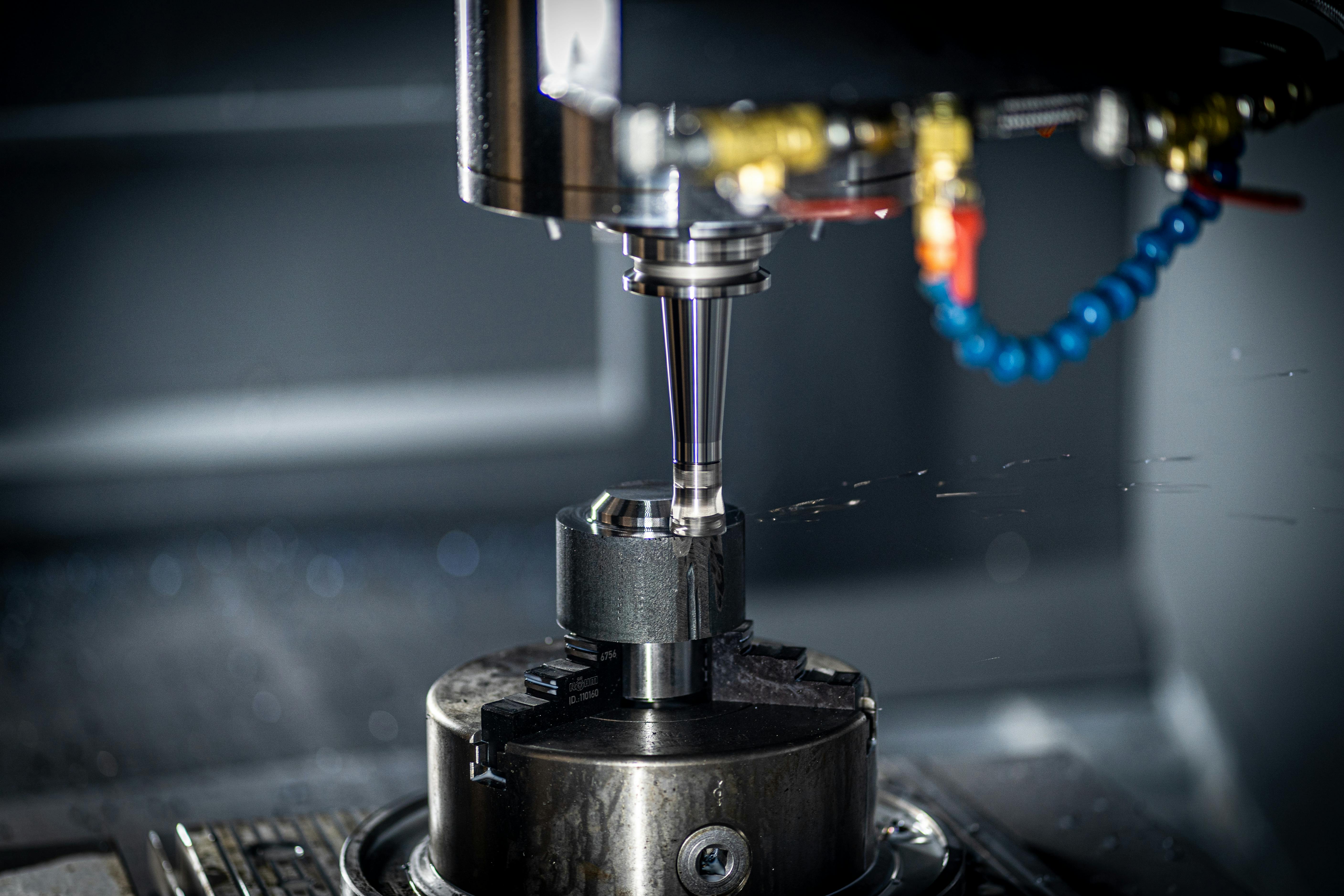
CNC typically becomes the correct answer when the question shifts from "is the form right?" to "does the real material with real feature tolerances behave as truly expected?" Machined polycarbonate, ABS, or glass-filled nylon provides designers with true thermoplastics that were previously approximated with photopolymers; machining also offers tighter tolerances (typical feature ±0.025 mm), which can reveal fit issues absorbed by additive manufacturing. Machining also introduces its own design logic: undercuts, tool paths, minimum internal radii—these are often new constraints for injection molding designers.
| Feature | Easy to Print | Exposed by Machining | Design Response |
|---|---|---|---|
| Internal Undercuts | Supports handled automatically | Requires 4/5-axis, or redesign | Move undercut to parting line or split part |
| Very Small Radii (under 0.5 mm) | Printable depending on layer thickness | Minimum tool radius limit | Set minimum radius to tool diameter × 1.5 |
| High Aspect Ratio Thin Walls (over 10:1) | Feasible by layering | Chatter; requires added rigidity | Re-evaluate necessity of thin walls |
| Threaded Holes | Can be tapped after printing | Direct tapping is more reliable | Design as self-tapping holes + post-tap |
| Flatness | Accumulated layer differences | Proper support with rigid fixtures | Add ribs or divide large flat parts |
Bridge Tooling—When the Question Is "How Does the Injection-Molded Part Behave?"
At a certain stage in a plastic project, unresolved questions shift from "shape/material" to "process-specific": gate location, weld lines, sink marks, draft, and appearance consistency that only manifests after 50 consecutive shots of the same part. Additive substitutes cannot answer these questions. The standard answer is usually bridge tooling—an aluminum mold expected to run 100–5,000 shots, taking 3–6 weeks to open and costing US$8,000–US$40,000, depending on complexity. This allows for injection molding of true sample parts with the final resin, without incurring the months-long cost of steel tooling. This is the stage where a project transitions from "prototype parts" to "prototype process."
| Quantity Scenario | Right Choice | Typical Total Cost |
|---|---|---|
| Design review 1–20 pieces | Additive prototypes | Total US$500–5,000 |
| 20–100 pieces needing molded appearance | PU casting from printed master | Tooling US$500–3,000 + per piece cost |
| 100–5,000 pieces for validation | Aluminum bridge tooling | Tooling US$10k–40k + US$5–40 per piece |
| 5,000–50,000 pieces | Aluminum or hybrid tooling, then transition | Tooling US$25k–80k + US$3–15 per piece |
| 50,000+ pieces | Hardened steel production tooling | Tooling US$40k–250k + US$0.50–8 per piece |
Aligning Prototyping Methods with Decision Stages
The most useful safeguard is to let prototype fidelity rise with the severity of the decisions. Early samples quickly weed out major errors; later samples focus on the few hard risks that remain after geometry and architecture have stabilized. Increasing fidelity before design is settled, or using conceptual parts after design is settled, are equally costly mistakes.
| Project Stage | Current Risk | Appropriate Prototyping Method |
|---|---|---|
| Concept / Early Design (Weeks 0–4) | Form, configuration, review buy-in | SLA or FDM—fast, cheap, material approximation sufficient |
| Fit and Function (Weeks 4–10) | Assembly, gaps, mechanical behavior | SLS / MJF Nylon; CNC for tight tolerances |
| Pre-tooling Validation (Weeks 10–16) | Material behavior, aesthetic decisions, thermal / UV | CNC with true resin; PU casting for aesthetics |
| Process Validation (Weeks 14–22) | Injection-specific effects (gates, weld lines, sink marks) | Bridge tooling—true injection-molded samples |
| Production Ramp-up | Tool life, aesthetic consistency at volume | Hardened steel tooling—production intent |
Application Cases
A project that disciplinedly climbed the ladder and shipped on time and budget
A medical device project spent 22 weeks taking a handheld diagnostic device from the first sketch to initial mass production. Weeks 1–4 used SLA concept models (six rounds, total US$1,200) to finalize the form; weeks 4–10 used SLS PA12 functional prototypes (three rounds, total US$4,600) to identify two interference issues and one button ergonomics problem—which would have been misread under the rough surface of FDM. Weeks 10–14 used four production-grade polycarbonate CNC prototypes (US$7,800) to verify the fit of latches and optical windows, tested under the true material stiffness. Weeks 14–20 involved opening an aluminum bridge mold (US$24,000 + US$12 per piece for 180 pieces) to validate gate locations, sink marks around the processor shield, and the aesthetic fit of actual injection-molded parts. Total prototyping cost within 22 weeks was approximately US$39,000—by the time the production steel mold was introduced, the project had answered geometry, material, and process-specific questions in the correct sequence. No single prototype was the most expensive; the absence of surprises was the key itself.
Key design action: The team resisted two temptations at each stage—upgrading fidelity too early (wanting "real materials" while the form was still in flux), and upgrading fidelity too late (hoping CNC could substitute for bridge tooling to save money). Neither shortcut works. The only reliable strategy is to let the current active risk dictate the method.
A counter-example of choosing the wrong CNC at the wrong time
An earlier, less disciplined version of a similar project took the opposite approach. The project manager insisted on CNC polycarbonate prototypes in week four, reasoning that "the plastic must be real." The prototypes cost US$16,500 and took three weeks to deliver; by the time they arrived, the team had already changed the grip geometry based on SLA review—making the CNC parts obsolete upon arrival. Worse, the machining's ±0.025 mm tolerance masked a sink mark issue (CNC doesn't have sink marks), a problem that later erupted in injection molding production, causing a US$42,000 mold rework. Real material is not necessarily the right answer; the right answer is the material that addresses the currently active problem.
Bridge tooling that saved a production mold rework
A consumer product project used aluminum bridge tooling in week 16—US$22,000, 500 shots—having been tempted to skip it and go straight to steel tooling to save four weeks. The bridge shot exposed two problems: weld lines visible on aesthetic surfaces, and sink marks next to thick bosses. Both were injection-flow specific issues, not visible in any previous additive or CNC parts. The team spent two weeks + US$3,000 modifying the gate and boss relief designs on the bridge mold, then cut the steel mold with the revised design. The steel mold cost US$78,000 and has been in stable production ever since. If they had skipped the bridge and gone straight to steel, fixing the weld lines alone would have required changing the mold core, quoted at US$34,000 + four weeks of production downtime—seven times the cost of the bridge mold correction.
Do / Don't Comparison
| Do | Don't |
|---|---|
| Choose prototyping methods based on current active risks | Choose based on habit, ego, or "real materials look better" |
| Let fidelity rise with decision severity | Jump to high fidelity before the form is settled |
| Budget for 3–5 prototyping stages | Budget for a one-off, "answer-all" prototype |
| Initiate bridge tooling when process effects dominate residual risks | Skip bridge tooling, expecting CNC to identify injection issues |
| Use true production resins for CNC | Use whatever resin is available and call it "real material" |
| Re-evaluate methods when risks change | Lock in the prototyping roadmap at project kickoff and don't revisit |
Common Mistakes and How to Avoid Them
| Mistake | Why It Fails | How to Avoid |
|---|---|---|
| Expecting ABS-like photopolymer behavior to equal injection-molded ABS | Resin approximation resembles appearance, not fatigue or impact | Reserve ABS-like for appearance/fit; use SLS Nylon or CNC for functional validation |
| Skipping bridge tooling to save time | Injection-specific defects only appear with true tooling | Do not cut steel molds if sink mark / weld line risks are unresolved |
| Buying precise CNC while form is still in flux | Parts may become obsolete before design freeze | Increase real material fidelity after form is frozen |
| Single piece prototypes (hero parts) | One part cannot represent batch or process consistency | Plan for multiple pieces; include batch consistency in acceptance criteria |
| Pushing all problems to the last prototyping round | All-encompassing parts lead to time pressure and information overload | Focus each round on one or two decisions |
| No phased budget planning | If one round overspends, later budget for fidelity increase disappears | Budget prototyping by phase, including buffers for each stage |
Pre-Submission Checklist
Go through this before sending out each prototype PO. It forces the team to clearly define "evidence to be obtained / method to be used / acceptance criteria"—the biggest predictor of "is this prototyping round worth doing."
- The active risks this prototyping round will address are clearly stated (form / fit / material / process).
- The chosen method corresponds to that risk, not to available equipment or habit.
- Fidelity is proportionate to decision severity—not too high, not too low.
- Acceptance criteria are defined before fabrication, not after parts arrive.
- The material on the PO corresponds to the evidence to be obtained (resin approximation vs. true thermoplastic vs. injection grade).
- The schedule reserves time for a second round with the same method (if new problems arise in the first round).
- The budget aligns with "sequential prototyping," not a single hero part.
- The next stage's method is pre-scoped, so no re-planning is needed for transition.
Design Summary
The best plastic prototyping strategy is not the fastest or cheapest—it's the one where each prototype addresses the currently active risk and advances the next decision. Early parts cheaply eliminate form risks; middle parts validate material and fit; late parts sweep up process-specific issues with true injection-molded parts. Any stage skipped or entered too early often incurs double the cost later on.


0 comments