
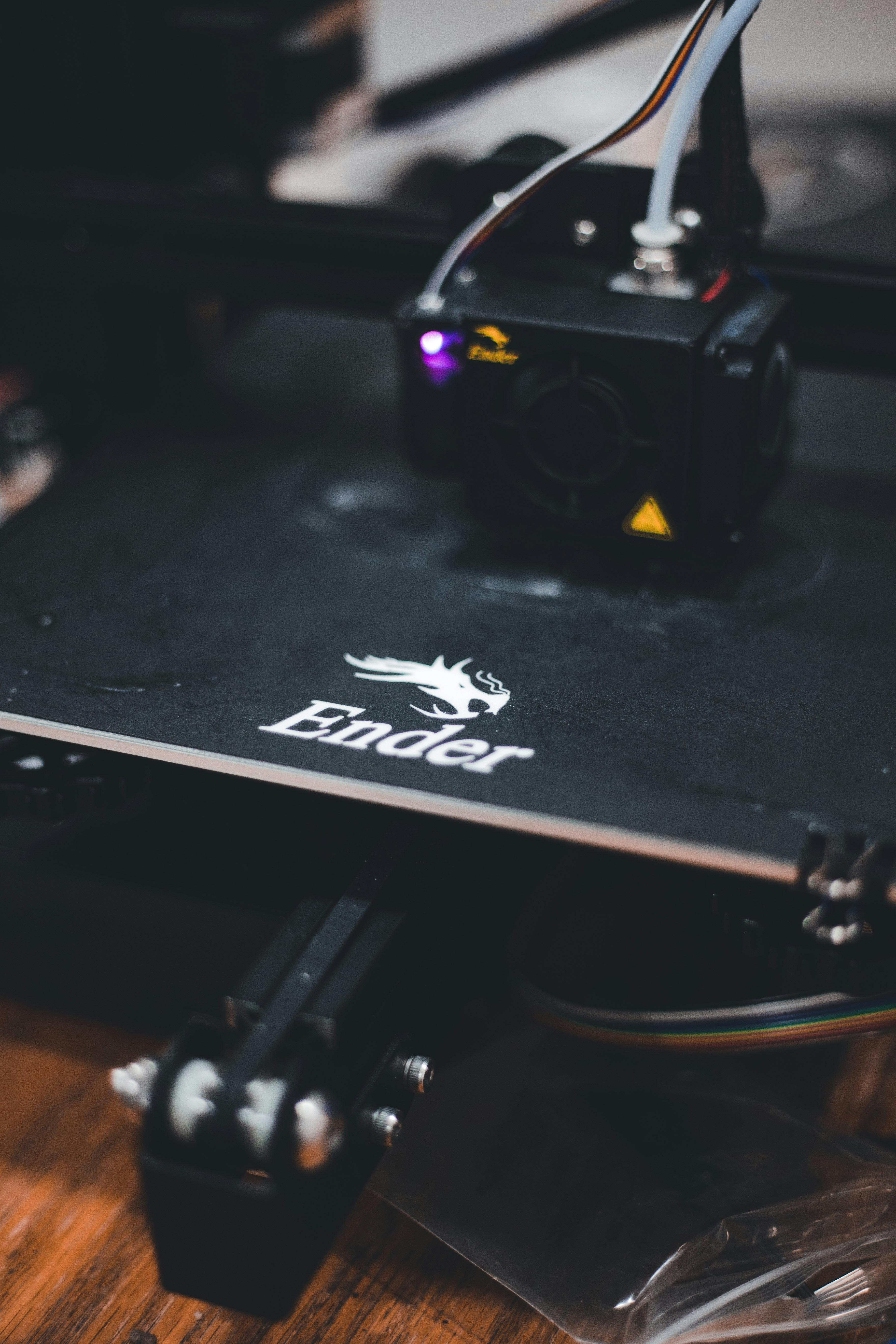
3D printing (or additive manufacturing) starts directly from CAD files, stacking parts layer by layer, cross-section by cross-section. Forty years have passed since Chuck Hull's stereolithography patent in 1984. It is no longer a novelty toy – the global market is projected to exceed USD 44 billion by 2026, covering models from USD 400 desktop FDM to USD 1,200,000 metal laser powder bed systems. What has truly changed is not just the printers, but the surrounding ecosystem of engineering-grade materials, DFM-aware software, and digital contract manufacturers who operate additive manufacturing as a mass production process.
This article is a map from an engineer's perspective: what the seven mainstream processes actually do, the materials suited for each process, where they will genuinely add value in 2026, and a section that most overviews skip – where they will subtly trip you up if you still design additive parts using the "drawing CNC parts" mindset.
What Actually Happens Inside the Machine
Every additive manufacturing process follows the same five logical steps – modeling, slicing, printing, post-processing, inspection – but the physical conditions under the nozzle or laser vary greatly. A design decision beneficial for process A might actually ruin the part in process B. SLA uses UV light to cure liquid photopolymers, with layer thicknesses of 25–100 μm; SLS uses a CO2 laser to sinter nylon powder, with layer thicknesses of 100–120 μm; FDM extrudes 0.4 mm thermoplastic filament; DMLS uses a 200–400 W fiber laser to weld metal powder into fully dense parts. Before choosing a process, you are essentially choosing "which failure mode" to deal with.
| Process | Typical Layer Thickness | Main Materials | Best Use Cases |
|---|---|---|---|
| SLA / DLP | 25–100 μm | Photopolymer Resin | Smooth aesthetic parts, dentistry |
| SLS | 100–120 μm | PA12 Nylon Powder | Functional plastic parts, small batch end-use parts |
| MJF | 80 μm | PA12, TPU, PA11 | End-use plastic parts, 10–10,000 units |
| FDM / FFF | 100–300 μm | PLA, ABS, PETG, PC | Jigs, fixtures, early concept parts |
| DMLS / SLM | 20–60 μm | Ti-6Al-4V, 17-4 PH, Inconel | Aerospace brackets, mold inserts |
| Binder Jetting | 80–100 μm | Stainless Steel, Sand, Ceramic | Metal parts 500+ units, USD 40–120/part |
| PolyJet | 16–32 μm | Multi-material photopolymers | Soft-touch aesthetic parts, anatomical models |
Where 3D Printing Truly Pays Off
Additive manufacturing truly wins when one of the following four conditions is met: quantity is below the tooling break-even point, geometry cannot be machined, lead time is measured in days, or each part must be unique. For a palm-sized PA12 casing, MJF is cheaper than injection molding for approximately 800–1,500 units; beyond this quantity, an aluminum mold costing USD 18,000–35,000 will be more cost-effective per unit. Knowing your part's crossover point is truly the first design decision.
| Quantity | Palm-sized PA12 unit cost | Mold cost | Lead Time |
|---|---|---|---|
| 1–10 (MJF) | USD 45–90 | USD 0 | 3–5 days |
| 50–200 (MJF) | USD 28–55 | USD 0 | 5–7 days |
| 500–1,500 (MJF) | USD 18–32 | USD 0 | 7–10 days |
| 2,000–10,000 (Aluminum mold injection molding) | USD 3.80–6.20 | USD 18,000–35,000 | 5–7 weeks |
| 50,000+ (Steel mold injection molding) | USD 1.20–2.40 | USD 45,000–90,000 | 8–12 weeks |
Choose Material First, Then Process
The quickest way to waste a week is to choose the process first, only to discover that the materials available for that process cannot withstand your operating temperature, chemical environment, or UV exposure. Please start with the load scenario. If you need continuous use at 120 °C, nylon SLS is out; you should look at PEEK FDM, high-temperature photopolymers, or go directly to metal. If the part needs to withstand repeated snap-fit flexing, MJF PA12 will last two orders of magnitude longer than SLA resin.
| Load Scenario | Recommended Choice | Avoid | Reason |
|---|---|---|---|
| Continuous 90 °C use | PA12-GF (MJF), PC (FDM) | Standard SLA resin | Resin HDT often 50–60 °C |
| Repeated living hinge flexing | PA12 (MJF/SLS) | SLA, PolyJet | Photopolymer fatigue life < 500 cycles |
| Transparent optical parts | Clear SLA, PolyJet VeroClear | MJF, SLS | Powder bed processes are opaque |
| Outdoor UV for 12+ months | ASA (FDM), PA11 (MJF) with coating | Untreated SLA resin | Yellowing, chalking |
| Medical skin contact | Biocompatible SLA (Class I) | Uncertified FDM filament | Regulatory traceability |
| Aerospace flight parts | Ti-6Al-4V (DMLS), PEEK (FDM) | Consumer-grade plastics | Existing certification basis |
Application Examples
An Aerospace Bracket That's 58% Lighter Without Losing Stiffness
A European satellite integrator originally machined an antenna bracket from a solid block of titanium alloy, weighing 412 grams per unit. For the entire project, every gram overweight incurred an approximately USD 9,500 launch mass cost. The original geometry was a solid casting with a large amount of material on multiple planes; machining accounted for 65% of the part, but structural analysis showed that only 22% of the material was actually under stress.
The critical design action: The team first put the bracket through topology optimization, then rebuilt it using DMLS Ti-6Al-4V, adding internal lattice ribs along the main stress directions. The final part came in at 173 grams, a 58% weight reduction, and the first modal frequency was 12% higher than the machined version, because material was removed from low-strain regions.
DMLS cost USD 2,850 per unit, compared to USD 1,900 for the machined version, meaning an increase in unit cost. However, calculated for a constellation of 120 satellites, the mass saved equates to USD 27,000,000 in launch capability, far exceeding the additional USD 114,000 part cost. Additive manufacturing stands viable because it shifts the optimization goal away from "can it be machined."
A Dental Lab Printing 480 Clear Aligners Daily with Two SLA Machines
A medium-sized clear aligner lab replaced its original "plaster mold + thermoforming" process with two SLA machines running overnight at 50 μm layer thickness. With an average of 24 different aligner shapes per case, the lab now delivers in 36 hours, compared to 5 days previously. The cost per aligner dropped from USD 11.40 to USD 4.20, including resin, cleaning, and UV post-curing. The USD 168,000 equipment investment was recouped in less than eleven months.
MJF-Printed Motorcycle Fairings Shipped in Batches of 220 for Paint Application
A European electric motorcycle startup needed 880 fairings in its first fourteen months – for this size, far below the reasonable break-even point for injection molding. They printed the fairings in four MJF sections, joined them, filled and sanded the surface, then wet-sprayed the topcoat. The cost per part, including paint, was USD 187; using tooling would have required a USD 62,000 steel mold and a nine-week wait. They delivered the first bike to the customer in the eleventh week after CAD freeze.
Designing for Additive Manufacturing Without Backing Yourself into a Corner
The most common mistake is directly transferring CNC habits – uniform wall thickness, symmetrical features, generous fillets – into additive manufacturing files. Additive manufacturing rewards ribs and lattices that follow stress paths, and unsupported overhangs within 45 degrees for polymers and 35 degrees for metals. It penalizes thin horizontal circular plates, enclosed powder cavities, and demanding 25 Ra surfaces.
| Do | Avoid |
|---|---|
| Orient critical surfaces upwards or sideways | Print aesthetic surfaces facing down on supports |
| Plastic wall thickness ≥ 0.8 mm, metal ≥ 0.5 mm | Walls below 0.4 mm in any process |
| Add ≥ 3 mm powder/liquid drain holes to enclosed cavities | Sealed pockets that trap powder or resin |
| Use chamfers instead of horizontal overhangs | Unsupported 90° overhangs exceeding 2 mm |
| Specify Ra only on necessary surfaces | Uniform 1.6 Ra for the entire part |
| Plan tolerance chains with ±0.2 mm / 100 mm | Assume machining tolerances of ±0.05 mm |
Common Mistakes in Every Novice Additive Design Review
| Mistake | Cause of Failure | How to Avoid |
|---|---|---|
| Treating STL tolerance as ±0.05 mm | Plastic processes only achieve ±0.2 mm at best | Allow 0.3–0.5 mm clearance for mating features |
| Uniform 2.5 mm wall thickness throughout the part | Wastes material and print time | Vary wall thickness between 0.8–2.0 mm based on stress fields |
| No drain holes in sealed enclosures | Each part traps 30–80 g of PA12 powder | Add 3 mm holes at low points |
| Directly specifying M3 machined threads | SLS threads strip at 4–6 N·m | Use heat-set inserts or direct tapping for M4 and above |
| Demanding A-class aesthetic on side walls | 0.12 mm layer thickness still shows layer lines | Add vapor polishing or painting |
| Drawing metal parts with CNC-style internal radii | 0.4 mm internal radii become 1.2 mm melt pools | Specify DMLS internal radii ≥ 1 mm |
Industry and Process Pairing
| Industry | Primary Process | Representative Parts | Source of Value |
|---|---|---|---|
| Aerospace | DMLS Titanium / Inconel | Brackets, fuel nozzles | Weight reduction + part consolidation |
| Medical | SLA + DMLS | Surgical guides, implants | Patient-specific geometry |
| Automotive | MJF + SLS | Interior fasteners, ducts | Volumes under 5,000 units |
| Consumer Electronics | MJF + SLA | Casings, trim | Weekly iterations |
| Industrial | SLS + FDM | Jigs, robotic end effectors | Lead time in days, not weeks |
| Dental | SLA / DLP | Aligner molds, crowns | One part per patient |
The Post-Processing Bill Nobody Tells You About in the Quote
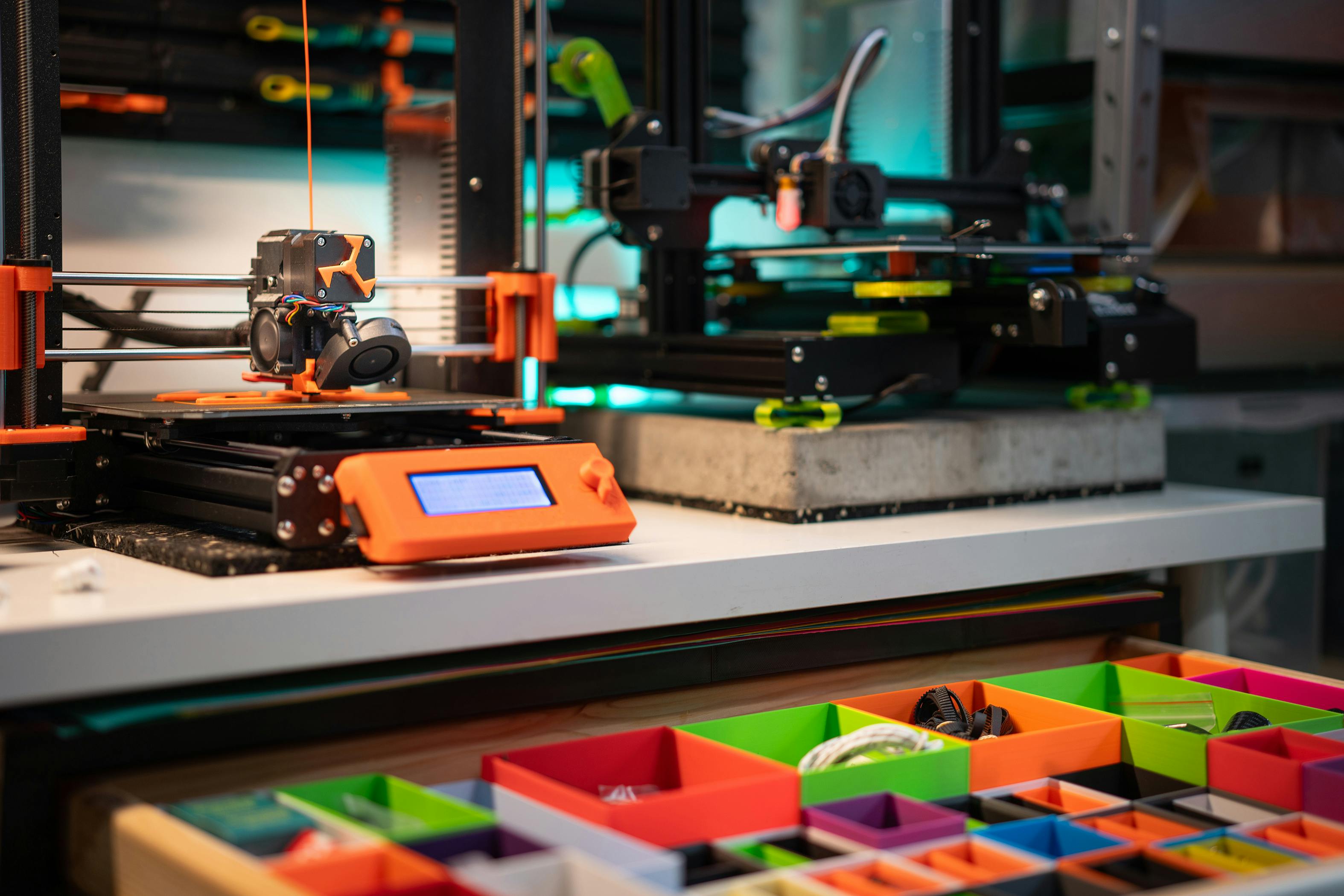
Parts fresh off the printer are almost never ready for shipment. SLA requires cleaning and UV post-curing, 20–40 minutes per batch; SLS/MJF requires powder removal and bead blasting, with vapor polishing adding another USD 3–8/part; DMLS requires support removal, 650 °C stress relief, and for flight parts, HIP (USD 180–400/part), with mating surfaces needing CNC finishing. For any functional part, add 25–45% to the quoted price for post-processing budget.
| Process | Required Steps | Additional Cost | Time |
|---|---|---|---|
| SLA | Cleaning + UV Post-Curing | USD 2–5 | 30 min |
| SLS | Powder Removal + Bead Blasting | USD 3–7 | 45 min |
| MJF | Powder Removal + Dyeing | USD 4–10 | 1 hr |
| DMLS | Stress Relief + Cutting + Finishing | USD 150–450 | 1–3 days |
| FDM | Support Removal + Sanding | USD 1–4 | 20 min |
Checklist Before Ordering
- Can you articulate the specific question this print run aims to answer?
- Does every wall thickness meet the lower limit of the chosen process?
- Do all enclosed volumes have powder/liquid drain holes of ≥ 3 mm?
- Is the print orientation based on critical surfaces, not fastest print time?
- Are tolerances only specified where functionally necessary, with ±0.2 mm assumed elsewhere?
- Has the material been validated for operating temperature, UV, and chemical environment?
- Are post-processing costs and lead times included in the project budget?
- Has the design review obtained quotes from at least two contract manufacturers?
Design Takeaways
In 2026, 3D printing isn't one technology, but a combination of seven processes, each with distinct physics, materials, and break-even points. Teams that truly win with additive manufacturing do three things: they pick the cheapest process that answers this week's question; they design for the failure modes of that specific process, not by reusing CNC habits; and they budget for post-processing from the first quote. By doing these three things, additive manufacturing ceases to be that "special item" on the quote sheet and becomes the shortest path from CAD to usable part.


0 comments