
A medical device startup delivered 420 nylon inhaler housings on an SLS line, with a landed cost of $11.80 each. Two weeks later, they moved the same geometry to MJF and changed the build orientation, producing 900 units at $7.30 each. The mechanical specifications were identical, and the appearance was almost the same. The only difference was: which powder bed fusion "dialect" was best suited for that geometry, and whether someone decided the answer before quoting.
Such cost discrepancies become common when teams stop treating powder bed fusion as a single process. PBF is actually a family, encompassing two branches (polymers and metals), various energy sources, and completely different design languages. This article focuses on how to align the design with the correct branch before the drawing leaves your hand.
Understanding the PBF Family at a Glance
PBF covers all processes that melt powder in a heated powder bed. On the polymer side, this includes SLS (laser), MJF (infrared plus fusing agent), and SBJ variants; on the metal side, it includes DMLS and SLM (fiber laser), EBM (electron beam), and the increasingly popular green light laser systems for copper. Each differs in melting mechanism, practical build volume, and design compromises.
The variant determines almost everything else: how layers are delineated, how residual stress accumulates, whether supports are needed, how powder is recycled, and how much the part will shrink or warp. Choosing the wrong variant for a geometry remains one of the most expensive upfront mistakes in PBF projects.
| Variant | Energy | Typical Materials | Supports Required | Primary Use |
|---|---|---|---|---|
| SLS | CO2 or Fiber Laser | PA12, PA11, PA-GF, TPU | No (powder acts as support) | Functional polymer parts |
| MJF | Infrared + Fusing Agent | PA12, PA11, PP, TPU | No | Mass-produced polymer parts |
| DMLS/SLM | Fiber Laser | 17-4PH, Ti6Al4V, AlSi10Mg, Inconel | Yes (anchors & thermal supports) | High-density metal parts |
| EBM | Electron Beam | Ti6Al4V, CoCr | Partial (sintered cake) | Medical, aerospace titanium |
| Green Light LPBF | Green Light Fiber Laser | Pure Cu, CuCrZr | Yes | Heat exchangers, induction coils |
Build Volume and Layer Thickness
Build volume determines stacking economics, and layer thickness determines surface quality and Z-axis resolution. Getting these two numbers right from the start avoids a common scenario: a part designed with nominal wall thickness, which, when sent to a service provider for actual machine build, is found to have a layer thickness that makes the nominal wall design "below threshold."
| Variant | Typical Build Plate (mm) | Layer Thickness (µm) | Notes |
|---|---|---|---|
| SLS | 340×340×600 | 80–120 | Heated bed approx. Tm-30°C |
| MJF | 380×284×380 | 80 | Uniform thermal field |
| DMLS/SLM | 250×250×325 | 20–60 | 30 µm is common default |
| EBM | 350×350×380 | 50–100 | Operates in vacuum chamber |
| Large-format LPBF | 600×600×600 | 60–90 | Multiple lasers with overlapping zones |
DFM Numbers Directly Applicable in CAD
The table below presents not manufacturer marketing figures, but ranges that numerous production factories will accept without additional review. Staying within these boundaries ensures a usable first build; deliberately exceeding them is possible but should be a conscious decision made after DFM discussion, not an accident.
| Feature | SLS/MJF (PA12) | DMLS (Metal) | Description |
|---|---|---|---|
| Min. Wall Thickness | 0.8 mm | 0.4 mm | Thinner walls will warp |
| Min. Assembly Clearance | 0.4 mm (per side) | 0.2 mm (per side) | Post-fusion state |
| Min. Hole Diameter | 0.5 mm | 0.3 mm | Consider depth-to-diameter ratio |
| Self-supporting Overhang Angle | N/A | 45° from build plate | |
| Powder Removal Hole | Ø4 mm | Ø3 mm | One per enclosed volume |
| Max. Unsupported Bridge | N/A | 2 mm | Longer will sag or curl |
| Min. Engraved Text | 0.8 mm deep | 0.4 mm deep | Sans-serif only |
Why PBF Can Produce Geometries Other Processes Cannot
Polymer PBF requires no supports because the surrounding powder cake supports the part during the build process. This explains why MJF and SLS dominate low-volume, end-use nylon parts: any geometry can be printed, there is no directional penalty, and assembly compatibility has minimal loss from CAD to build. This makes living hinges, undercuts, and nested parts not just possible, but inexpensive.
Metal PBF, however, is not support-free. High-density melt pools shrink and pull on the build plate, so anchors and thermal supports are still required for angles below approximately 45 degrees. The true value of metal PBF lies in part integration – a lattice-optimized Ti bracket, manufactured by any traditional method, would cost far more than DMLS, but on DMLS, it's about the same as the simplest equivalent block.
| Geometry | Traditional Manufacturing Cost | PBF Cost | Typical Ratio |
|---|---|---|---|
| Conformal Cooling Inserts | High (EDM + welding) | Medium (DMLS) | PBF approx. 0.6x |
| Topology Optimized Bracket | Very High (5-axis + welding) | Medium (DMLS) | PBF approx. 0.4x |
| Gyroid Heat Exchanger | Impractical | Medium (LPBF) | PBF only |
| Nested Mass Production Snap-fits | High (requires molds) | Low (MJF) | PBF approx. 0.3x for quantities < 2k |
Post-Processing is Part of the Design Itself
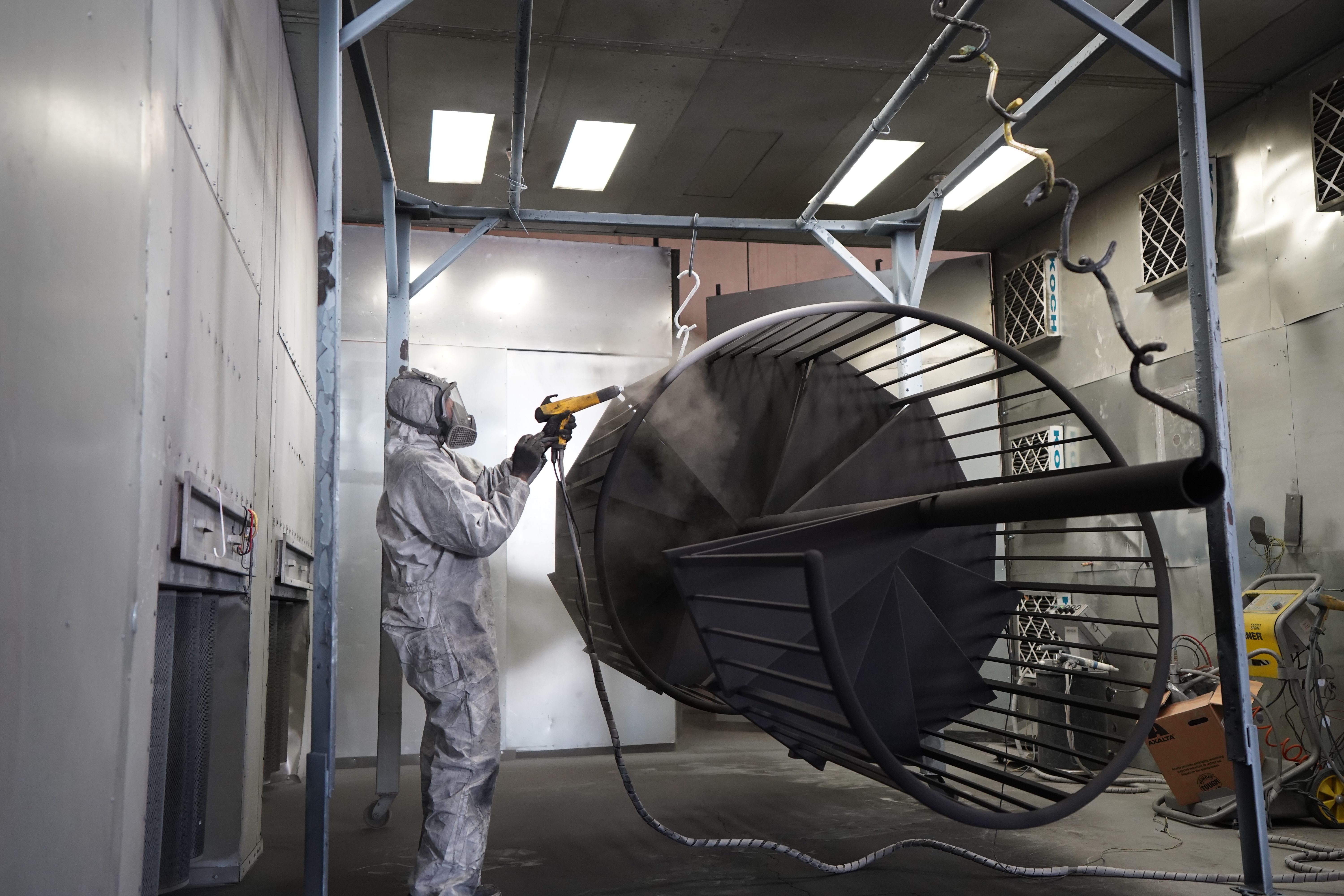
PBF parts rarely come out of the build chamber as finished products. Polymer parts typically undergo powder removal, sandblasting, optional dyeing or vapor smoothing, and dimensional verification; metal parts also require in-situ stress relief on the plate, wire EDM separation from the plate, support removal, optional Hot Isostatic Pressing (HIP), and CNC post-machining for functional surfaces. Treating post-processing as an afterthought is the most common source of delays or cost overruns for PBF parts.
| Step | Polymer PBF | Metal PBF | Typical Time |
|---|---|---|---|
| Cooling | 8–24 hours | 4–12 hours | Passive |
| Powder Removal | Manual brushing + air blast | Vacuum + brushing | 0.5–2 hours/part |
| Stress Relief | N/A | In-situ 600–900°C | 4–8 hours |
| Support Removal | N/A | Manual + wire EDM | 1–6 hours/part |
| Surface Treatment | Sandblasting, dyeing | Sandblasting, tumbling, polishing | 1–4 hours/part |
| Inspection | Calipers, 3D scanning | CMM, CT, fluorescent penetrant | Depends on part |
Application Scenarios Where PBF Truly Excels
The following three examples are not theoretical, but rather decision points that repeatedly emerge during quote reviews, determining whether a part will ultimately be profitable.
Respirator Housing Saved by MJF, Not SLS
A Class II respirator housing for a 900-piece pilot run was initially quoted at $14.20 per piece using SLS PA12, with a 12-day lead time. The geometry included a 1.0 mm living hinge that failed after 80 cycles due to SLS layer lines being perpendicular to the hinge axis. The engineering team transferred the same STL to MJF and reoriented the hinge to align with the fusing agent direction, increasing cycle life to over 5,000 cycles.
Key design action: The PBF variant should be chosen based on the primary stress axis, not just the quote. MJF's relatively isotropic mechanical response and thinner 80 µm layer thickness made the same wall thickness compliant. The CAD time spent on reorientation was zero, yet it saved the entire pilot production schedule.
Drone Titanium Bracket Outperforming 5-axis CNC with DMLS
A topology-optimized Ti6Al4V mounting bracket for a fixed-wing drone was initially machined from solid billet using CNC, costing $312 per piece, with 58% of the material becoming chips. The team switched to DMLS, stacking 6 parts per build on a 250x250 build plate. After HIP, stress relief, and CNC post-machining for two bolt mating surfaces, the landed cost was $148 per piece. The buy-to-fly ratio decreased from 5.4 to 1.3, and the stiffness-to-weight ratio improved by 21%.
LPBF Heat Exchanger Scrapped Due to Trapped Powder
A CuCrZr cold plate with 1.2 mm internal channels was perfectly built on a green light LPBF machine. However, after powder removal, two of the four channels were completely blocked by sintered powder because the only powder exit path involved a 90-degree turn and lacked ventilation. A second build added two Ø3 mm powder removal holes, which were plugged with threaded inserts after cleaning. This added $4 per piece but prevented a $9,200 scrap event.
Do / Don't Checklist
| Topic | Recommended Practice | Avoid |
|---|---|---|
| Variant Selection | Specify SLS/MJF/DMLS/LPBF before CAD finalization | Designing for generic "PBF" |
| Wall Thickness | Polymers ≥0.8 mm, Metals ≥0.4 mm | Pushing theoretical machine limits |
| Enclosed Volumes | Add Ø3–4 mm powder removal holes for each cavity | Assuming powder will self-clear around corners |
| Overhangs (Metal) | Maintain self-supporting angles above 45° | Expecting good surface quality on undersides |
| Orientation | Align primary stress direction with XY build plane | Leaving orientation to service provider's default |
| Surface Annotation | Clearly specify Ra range | Assuming as-built Ra meets functional requirements |
| Inspection | Budget for CT or CMM for critical metal parts | Trusting first-off as-built geometry |
Common Mistakes and How to Avoid Them
| Mistake | Why it's a problem | How to avoid |
|---|---|---|
| No powder removal holes for enclosed lattice | Sintered powder inside cannot be removed | Add Ø3–4 mm powder removal holes for each enclosed cavity |
| SLS living hinge oriented along layer direction | Z-anisotropy leads to cyclic bending failure | Switch to MJF or reorient hinge axis to XY |
| DMLS stress relief omitted | Residual stress causes warpage after wire EDM | Complete stress relief cycle while on the plate |
| Sealing surfaces only specify as-built Ra | As-built Ra 6–12 µm leaks with O-rings | Add CNC or grinding step for sealing surfaces |
| No thermal clearance in stacking | Local overheating affects adjacent parts | Leave at least 5 mm between parts, avoid stacking |
| Only trust first-off CMM | Porosity in internal channels is undetected | Add CT scan for fatigue-critical parts |
Pre-Build Checklist
Run through this checklist before sending your STL or STEP file for a quote. Every item on this list has caused at least one real-world build failure; checking is cheap, missing is expensive.
- PBF variant (SLS / MJF / DMLS / LPBF / EBM) is specified on the drawing.
- Primary stress axis is in the XY build plane, not along the Z-axis.
- All enclosed volumes have at least one Ø3–4 mm powder removal hole.
- Metal overhangs below 45° are shown with supports in the build-prep diagram.
- Wall thickness is 0.8 mm or greater for polymers / 0.4 mm or greater for metals.
- Sealing, bearing, and mating surfaces have 0.3–0.5 mm machining allowance.
- Inspection plan for fatigue-critical metal parts specifies CMM, CT, or fluorescent penetrant.
- Surface annotations clearly specify Ra range, not "smooth" or "clean."
Design Takeaways
Powder bed fusion is not a single answer, nor is it a universal solution. Each variant, material, and post-processing chain has its own design language. The teams that truly succeed with PBF parts are those that choose the right "dialect" before CAD freeze. Specify the variant early, align stresses with the build plane, treat powder removal and inspection as budget items as important as printing, and consider every enclosed volume as a space that must be cleaned. Get these four things right, and PBF will no longer be a gamble, but a reliable path to geometries that other processes simply cannot deliver.
0 comments